Classes | |
| struct | mpu6050_raw_acceleration_t |
| struct | mpu6050_raw_rotation_t |
| struct | mpu6050_acceleration_t |
| struct | mpu6050_rotation_t |
| struct | mpu6050_dev_t |
Macros | |
| #define | MPU6050_I2C_ADDRESS_LOW (0x68) |
| #define | MPU6050_I2C_ADDRESS_HIGH (0x69) |
Functions | |
| esp_err_t | mpu6050_init_desc (mpu6050_dev_t *dev, uint8_t addr, i2c_port_t port, gpio_num_t sda_gpio, gpio_num_t scl_gpio) |
| Initialize device descriptor. | |
| esp_err_t | mpu6050_free_desc (mpu6050_dev_t *dev) |
| Free device descriptor. | |
| esp_err_t | mpu6050_init (mpu6050_dev_t *dev) |
| Initialize device. | |
| esp_err_t | mpu6050_get_aux_vddio_level (mpu6050_dev_t *dev, mpu6050_vddio_level_t *level) |
| Get the auxiliary I2C supply voltage level. | |
| esp_err_t | mpu6050_set_aux_vddio_level (mpu6050_dev_t *dev, mpu6050_vddio_level_t level) |
| Set the auxiliary I2C supply voltage level. | |
| esp_err_t | mpu6050_get_rate (mpu6050_dev_t *dev, uint8_t *rate) |
| Get gyroscope output rate divider. | |
| esp_err_t | mpu6050_set_rate (mpu6050_dev_t *dev, uint8_t rate) |
| Set gyroscope output rate divider. | |
| esp_err_t | mpu6050_get_external_frame_sync (mpu6050_dev_t *dev, mpu6050_ext_sync_t *sync) |
| Get external FSYNC configuration. | |
| esp_err_t | mpu6050_set_external_frame_sync (mpu6050_dev_t *dev, mpu6050_ext_sync_t sync) |
| Set external FSYNC configuration. | |
| esp_err_t | mpu6050_get_dlpf_mode (mpu6050_dev_t *dev, mpu6050_dlpf_mode_t *mode) |
| Get digital low-pass filter configuration. | |
| esp_err_t | mpu6050_set_dlpf_mode (mpu6050_dev_t *dev, mpu6050_dlpf_mode_t mode) |
| Set digital low-pass filter configuration. | |
| esp_err_t | mpu6050_get_full_scale_gyro_range (mpu6050_dev_t *dev, mpu6050_gyro_range_t *gyro_range) |
| Get full-scale gyroscope range. | |
| esp_err_t | mpu6050_set_full_scale_gyro_range (mpu6050_dev_t *dev, mpu6050_gyro_range_t range) |
| Set full-scale gyroscope range. | |
| esp_err_t | mpu6050_get_accel_self_test_factory_trim (mpu6050_dev_t *dev, mpu6050_axis_t axis, uint8_t *trim) |
| Get self-test factory trim value for accelerometer axis. | |
| esp_err_t | mpu6050_get_gyro_self_test_factory_trim (mpu6050_dev_t *dev, mpu6050_axis_t axis, uint8_t *trim) |
| Get self-test factory trim value for gyroscope axis. | |
| esp_err_t | mpu6050_get_accel_self_test (mpu6050_dev_t *dev, mpu6050_axis_t axis, bool *enabled) |
| Get self-test enabled for accelerometer axis. | |
| esp_err_t | mpu6050_set_accel_self_test (mpu6050_dev_t *dev, mpu6050_axis_t axis, bool enabled) |
| Set self-test enabled for accelerometer axis. | |
| esp_err_t | mpu6050_get_full_scale_accel_range (mpu6050_dev_t *dev, mpu6050_accel_range_t *range) |
| Get full-scale accelerometer range. | |
| esp_err_t | mpu6050_set_full_scale_accel_range (mpu6050_dev_t *dev, mpu6050_accel_range_t range) |
| Set full-scale accelerometer range. | |
| esp_err_t | mpu6050_get_dhpf_mode (mpu6050_dev_t *dev, mpu6050_dhpf_mode_t *mode) |
| Get the high-pass filter configuration. The DHPF is a filter module in the path leading to motion detectors (Free Fall, Motion threshold, and Zero Motion). The high pass filter output is not available to the data registers. | |
| esp_err_t | mpu6050_set_dhpf_mode (mpu6050_dev_t *dev, mpu6050_dhpf_mode_t mode) |
| Set the high-pass filter configuration. | |
| esp_err_t | mpu6050_get_freefall_detection_threshold (mpu6050_dev_t *dev, uint8_t *threshold) |
| Get free-fall event acceleration threshold. | |
| esp_err_t | mpu6050_set_freefall_detection_threshold (mpu6050_dev_t *dev, uint8_t threshold) |
| Get free-fall event acceleration threshold. | |
| esp_err_t | mpu6050_get_freefall_detection_duration (mpu6050_dev_t *dev, uint8_t *duration_ms) |
| Get free-fall event duration threshold. | |
| esp_err_t | mpu6050_set_freefall_detection_duration (mpu6050_dev_t *dev, uint8_t duration_ms) |
| Set free-fall event duration threshold. | |
| esp_err_t | mpu6050_get_motion_detection_threshold (mpu6050_dev_t *dev, uint8_t *threshold) |
| Get motion detection event acceleration threshold. | |
| esp_err_t | mpu6050_set_motion_detection_threshold (mpu6050_dev_t *dev, uint8_t threshold) |
| Set motion detection event acceleration threshold. | |
| esp_err_t | mpu6050_get_motion_detection_duration (mpu6050_dev_t *dev, uint8_t *duration) |
| Get motion detection event duration threshold. | |
| esp_err_t | mpu6050_set_motion_detection_duration (mpu6050_dev_t *dev, uint8_t duration) |
| Set motion detection event duration threshold. | |
| esp_err_t | mpu6050_get_zero_motion_detection_threshold (mpu6050_dev_t *dev, uint8_t *threshold) |
| Get zero motion detection event acceleration threshold. | |
| esp_err_t | mpu6050_set_zero_motion_detection_threshold (mpu6050_dev_t *dev, uint8_t threshold) |
| Set zero motion detection event acceleration threshold. | |
| esp_err_t | mpu6050_get_zero_motion_detection_duration (mpu6050_dev_t *dev, uint8_t *duration) |
| Get zero motion detection event duration threshold. | |
| esp_err_t | mpu6050_set_zero_motion_detection_duration (mpu6050_dev_t *dev, uint8_t duration) |
| Set zero motion detection event duration threshold. | |
| esp_err_t | mpu6050_get_temp_fifo_enabled (mpu6050_dev_t *dev, bool *enabled) |
| Get temperature FIFO enabled value. | |
| esp_err_t | mpu6050_set_temp_fifo_enabled (mpu6050_dev_t *dev, bool enabled) |
| Set temperature FIFO enabled value. | |
| esp_err_t | mpu6050_get_gyro_fifo_enabled (mpu6050_dev_t *dev, mpu6050_axis_t axis, bool *enabled) |
| Get gyroscope axis FIFO enabled value. | |
| esp_err_t | mpu6050_set_gyro_fifo_enabled (mpu6050_dev_t *dev, mpu6050_axis_t axis, bool enabled) |
| Set gyroscope axis FIFO enabled value. | |
| esp_err_t | mpu6050_get_accel_fifo_enabled (mpu6050_dev_t *dev, bool *enabled) |
| Get accelerometer FIFO enabled value. | |
| esp_err_t | mpu6050_set_accel_fifo_enabled (mpu6050_dev_t *dev, bool enabled) |
| Set accelerometer FIFO enabled value. | |
| esp_err_t | mpu6050_get_slave_fifo_enabled (mpu6050_dev_t *dev, mpu6050_slave_t num, bool *enabled) |
| Get Slave FIFO enabled value. | |
| esp_err_t | mpu6050_set_slave_fifo_enabled (mpu6050_dev_t *dev, mpu6050_slave_t num, bool enabled) |
| Set Slave FIFO enabled value. | |
| esp_err_t | mpu6050_get_multi_master_enabled (mpu6050_dev_t *dev, bool *enabled) |
| Get multi-master enabled value. | |
| esp_err_t | mpu6050_set_multi_master_enabled (mpu6050_dev_t *dev, bool enabled) |
| Set multi-master enabled value. | |
| esp_err_t | mpu6050_get_wait_for_external_sensor_enabled (mpu6050_dev_t *dev, bool *enabled) |
| Get wait-for-external-sensor-data enabled value. | |
| esp_err_t | mpu6050_set_wait_for_external_sensor_enabled (mpu6050_dev_t *dev, bool enabled) |
| Set wait-for-external-sensor-data enabled value. | |
| esp_err_t | mpu6050_get_slave_read_write_transition_enabled (mpu6050_dev_t *dev, bool *enabled) |
| Get slave read/write transition enabled value. | |
| esp_err_t | mpu6050_set_slave_read_write_transition_enabled (mpu6050_dev_t *dev, bool enabled) |
| Set slave read/write transition enabled value. | |
| esp_err_t | mpu6050_get_master_clock_speed (mpu6050_dev_t *dev, mpu6050_i2c_master_clock_t *clk_spd) |
| Get I2C master clock speed. | |
| esp_err_t | mpu6050_set_master_clock_speed (mpu6050_dev_t *dev, mpu6050_i2c_master_clock_t clk_spd) |
| Set I2C master clock speed. | |
| esp_err_t | mpu6050_get_slave_address (mpu6050_dev_t *dev, mpu6050_slave_t num, uint8_t *addr) |
| Get the I2C address of the specified slave. | |
| esp_err_t | mpu6050_set_slave_address (mpu6050_dev_t *dev, mpu6050_slave_t num, uint8_t address) |
| Set the I2C address of the specified slave. | |
| esp_err_t | mpu6050_get_slave_register (mpu6050_dev_t *dev, mpu6050_slave_t num, uint8_t *reg) |
| Get the active internal register for the specified slave. | |
| esp_err_t | mpu6050_set_slave_register (mpu6050_dev_t *dev, mpu6050_slave_t num, uint8_t reg) |
| Set the active internal register for the specified slave. | |
| esp_err_t | mpu6050_get_slave_enabled (mpu6050_dev_t *dev, mpu6050_slave_t num, bool *enabled) |
| Get the enabled value for the specified slave. | |
| esp_err_t | mpu6050_set_slave_enabled (mpu6050_dev_t *dev, mpu6050_slave_t num, bool enabled) |
| Set the enabled value for the specified slave. | |
| esp_err_t | mpu6050_get_slave_word_byte_swap (mpu6050_dev_t *dev, mpu6050_slave_t num, bool *enabled) |
| Get word pair byte-swapping enabled for the specified slave. | |
| esp_err_t | mpu6050_set_slave_word_byte_swap (mpu6050_dev_t *dev, mpu6050_slave_t num, bool enabled) |
| Set word pair byte-swapping enabled for the specified slave. | |
| esp_err_t | mpu6050_get_slave_write_mode (mpu6050_dev_t *dev, mpu6050_slave_t num, bool *mode) |
| Get write mode for the specified slave. | |
| esp_err_t | mpu6050_set_slave_write_mode (mpu6050_dev_t *dev, mpu6050_slave_t num, bool mode) |
| Set write mode for the specified slave. | |
| esp_err_t | mpu6050_get_slave_word_group_offset (mpu6050_dev_t *dev, mpu6050_slave_t num, bool *enabled) |
| Get word pair grouping order offset for the specified slave. | |
| esp_err_t | mpu6050_set_slave_word_group_offset (mpu6050_dev_t *dev, mpu6050_slave_t num, bool enabled) |
| Set word pair grouping order offset for the specified slave. | |
| esp_err_t | mpu6050_get_slave_data_length (mpu6050_dev_t *dev, mpu6050_slave_t num, uint8_t *length) |
| Get number of bytes to read for the specified slave. | |
| esp_err_t | mpu6050_set_slave_data_length (mpu6050_dev_t *dev, mpu6050_slave_t num, uint8_t length) |
| Set number of bytes to read for the specified slave. | |
| esp_err_t | mpu6050_set_slave_4_output_byte (mpu6050_dev_t *dev, uint8_t data) |
| Set new byte to write to Slave 4. This register stores the data to be written into the Slave 4. If I2C_SLV4_RW is set 1 (set to read), this register has no effect. | |
| esp_err_t | mpu6050_get_slave_4_interrupt_enabled (mpu6050_dev_t *dev, bool *enabled) |
| Get the enabled value for Slave 4 transaction interrupts. | |
| esp_err_t | mpu6050_set_slave_4_interrupt_enabled (mpu6050_dev_t *dev, bool enabled) |
| Set the enabled value for Slave 4 transaction interrupts. | |
| esp_err_t | mpu6050_get_slave_4_master_delay (mpu6050_dev_t *dev, uint8_t *delay) |
| Get Slave 4 master delay value. | |
| esp_err_t | mpu6050_set_slave_4_master_delay (mpu6050_dev_t *dev, uint8_t delay) |
| Set Slave 4 master delay value. | |
| esp_err_t | mpu6050_get_slave_4_input_byte (mpu6050_dev_t *dev, uint8_t *byte) |
| Get last available byte read from Slave 4. | |
| esp_err_t | mpu6050_get_passthrough_status (mpu6050_dev_t *dev, bool *enabled) |
| Get FSYNC interrupt status. | |
| esp_err_t | mpu6050_get_slave_4_is_done (mpu6050_dev_t *dev, bool *enabled) |
| Get Slave 4 transaction done status. | |
| esp_err_t | mpu6050_get_lost_arbitration (mpu6050_dev_t *dev, bool *lost) |
| Get master arbitration lost status. | |
| esp_err_t | mpu6050_get_slave_nack (mpu6050_dev_t *dev, mpu6050_slave_t num, bool *nack) |
| Get Slave NACK status. | |
| esp_err_t | mpu6050_get_interrupt_mode (mpu6050_dev_t *dev, mpu6050_int_level_t *mode) |
| Get interrupt logic level mode. | |
| esp_err_t | mpu6050_set_interrupt_mode (mpu6050_dev_t *dev, mpu6050_int_level_t mode) |
| Set interrupt logic level mode. | |
| esp_err_t | mpu6050_get_interrupt_drive (mpu6050_dev_t *dev, mpu6050_int_drive_t *drive) |
| Get interrupt drive mode. | |
| esp_err_t | mpu6050_set_interrupt_drive (mpu6050_dev_t *dev, mpu6050_int_drive_t drive) |
| Set interrupt drive mode. | |
| esp_err_t | mpu6050_get_interrupt_latch (mpu6050_dev_t *dev, mpu6050_int_latch_t *latch) |
| Get interrupt latch mode. | |
| esp_err_t | mpu6050_set_interrupt_latch (mpu6050_dev_t *dev, mpu6050_int_latch_t latch) |
| Set interrupt latch mode. | |
| esp_err_t | mpu6050_get_interrupt_latch_clear (mpu6050_dev_t *dev, bool *clear) |
| Get interrupt latch clear mode. | |
| esp_err_t | mpu6050_set_interrupt_latch_clear (mpu6050_dev_t *dev, bool clear) |
| Set interrupt latch clear mode. | |
| esp_err_t | mpu6050_get_fsync_interrupt_level (mpu6050_dev_t *dev, mpu6050_int_level_t *level) |
| Get FSYNC interrupt logic level. | |
| esp_err_t | mpu6050_set_fsync_interrupt_level (mpu6050_dev_t *dev, mpu6050_int_level_t level) |
| Set FSYNC interrupt logic level. | |
| esp_err_t | mpu6050_get_fsync_interrupt_enabled (mpu6050_dev_t *dev, bool *enabled) |
| Get FSYNC pin interrupt enabled setting. | |
| esp_err_t | mpu6050_set_fsync_interrupt_enabled (mpu6050_dev_t *dev, bool enabled) |
| Set FSYNC pin interrupt enabled setting. | |
| esp_err_t | mpu6050_get_i2c_bypass_enabled (mpu6050_dev_t *dev, bool *enabled) |
| Get I2C bypass enabled status. | |
| esp_err_t | mpu6050_set_i2c_bypass_enabled (mpu6050_dev_t *dev, bool enabled) |
| Set I2C bypass enabled status. | |
| esp_err_t | mpu6050_get_clock_output_enabled (mpu6050_dev_t *dev, bool *enabled) |
| Get reference clock output enabled status. | |
| esp_err_t | mpu6050_set_clock_output_enabled (mpu6050_dev_t *dev, bool enabled) |
| Set reference clock output enabled status. | |
| esp_err_t | mpu6050_get_int_enabled (mpu6050_dev_t *dev, uint8_t *ints) |
| Get full interrupt enabled status. | |
| esp_err_t | mpu6050_set_int_enabled (mpu6050_dev_t *dev, uint8_t ints) |
| Set full interrupt enabled status. | |
| esp_err_t | mpu6050_get_int_status (mpu6050_dev_t *dev, uint8_t *ints) |
| Get full set of interrupt status bits. | |
| esp_err_t | mpu6050_get_accel_offset (mpu6050_dev_t *dev, mpu6050_axis_t axis, int16_t *offset) |
| Get offset for accelerometer axis. | |
| esp_err_t | mpu6050_set_accel_offset (mpu6050_dev_t *dev, mpu6050_axis_t axis, int16_t offset) |
| Set offset for accelerometer axis. | |
| esp_err_t | mpu6050_get_gyro_offset (mpu6050_dev_t *dev, mpu6050_axis_t axis, int16_t *offset) |
| Get offset for gyroscope axis. | |
| esp_err_t | mpu6050_set_gyro_offset (mpu6050_dev_t *dev, mpu6050_axis_t axis, int16_t offset) |
| Get offset for gyroscope axis. | |
| esp_err_t | mpu6050_get_acceleration (mpu6050_dev_t *dev, mpu6050_acceleration_t *accel) |
| Get 3-axis accelerometer readings. | |
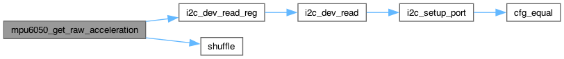
| esp_err_t | mpu6050_get_raw_acceleration (mpu6050_dev_t *dev, mpu6050_raw_acceleration_t *raw_accel) |
| Get raw 3-axis accelerometer readings. | |
| esp_err_t | mpu6050_get_acceleration_axis (mpu6050_dev_t *dev, mpu6050_axis_t axis, float *accel) |
| Get accelerometer reading on a single axis. | |
| esp_err_t | mpu6050_get_raw_acceleration_axis (mpu6050_dev_t *dev, mpu6050_axis_t axis, int16_t *raw_accel) |
| Get raw accelerometer reading on a single axis. | |
| esp_err_t | mpu6050_get_temperature (mpu6050_dev_t *dev, float *temp) |
| Get current internal temperature. | |
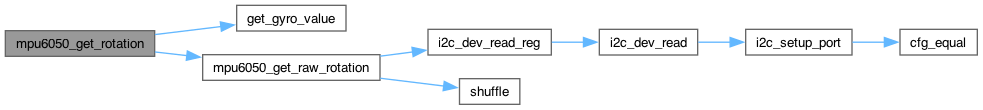
| esp_err_t | mpu6050_get_rotation (mpu6050_dev_t *dev, mpu6050_rotation_t *gyro) |
| Get 3-axis gyroscope readings. | |
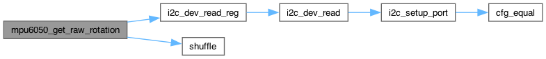
| esp_err_t | mpu6050_get_raw_rotation (mpu6050_dev_t *dev, mpu6050_raw_rotation_t *raw_gyro) |
| Get raw 3-axis gyroscope readings. | |
| esp_err_t | mpu6050_get_rotation_axis (mpu6050_dev_t *dev, mpu6050_axis_t axis, float *gyro) |
| Get gyroscope reading on a single axis. | |
| esp_err_t | mpu6050_get_raw_rotation_axis (mpu6050_dev_t *dev, mpu6050_axis_t axis, int16_t *raw_gyro) |
| Get raw gyroscope reading on a single axis. | |
| esp_err_t | mpu6050_get_motion (mpu6050_dev_t *dev, mpu6050_acceleration_t *data_accel, mpu6050_rotation_t *data_gyro) |
| Get raw 6-axis motion sensor readings (accel/gyro). | |
| esp_err_t | mpu6050_get_external_sensor_data (mpu6050_dev_t *dev, int position, void *buf, size_t length) |
| Read bytes from external sensor data register. | |
| esp_err_t | mpu6050_get_motion_status (mpu6050_dev_t *dev, uint8_t *status) |
| Get full motion detection status register content (all bits). | |
| esp_err_t | mpu6050_set_slave_output_byte (mpu6050_dev_t *dev, mpu6050_slave_t num, uint8_t data) |
| Write byte to Data Output container for specified slave. | |
| esp_err_t | mpu6050_get_external_shadow_delay_enabled (mpu6050_dev_t *dev, bool *enabled) |
| Get external data shadow delay enabled status. | |
| esp_err_t | mpu6050_set_external_shadow_delay_enabled (mpu6050_dev_t *dev, bool enabled) |
| Set external data shadow delay enabled status. | |
| esp_err_t | mpu6050_get_slave_delay_enabled (mpu6050_dev_t *dev, mpu6050_slave_t num, bool *enabled) |
| Get slave delay enabled status. | |
| esp_err_t | mpu6050_set_slave_delay_enabled (mpu6050_dev_t *dev, mpu6050_slave_t num, bool enabled) |
| Set slave delay enabled status. | |
| esp_err_t | mpu6050_reset_gyroscope_path (mpu6050_dev_t *dev) |
| Reset gyroscope signal path. | |
| esp_err_t | mpu6050_reset_accelerometer_path (mpu6050_dev_t *dev) |
| Reset accelerometer signal path. | |
| esp_err_t | mpu6050_reset_temperature_path (mpu6050_dev_t *dev) |
| Reset temperature sensor signal path. | |
| esp_err_t | mpu6050_get_accelerometer_power_on_delay (mpu6050_dev_t *dev, uint8_t *delay) |
| Get accelerometer power-on delay. | |
| esp_err_t | mpu6050_set_accelerometer_power_on_delay (mpu6050_dev_t *dev, uint8_t delay) |
| Set accelerometer power-on delay. | |
| esp_err_t | mpu6050_get_freefall_detection_counter_decrement (mpu6050_dev_t *dev, uint8_t *decrement) |
| Get Free Fall detection counter decrement configuration. | |
| esp_err_t | mpu6050_set_freefall_detection_counter_decrement (mpu6050_dev_t *dev, uint8_t decrement) |
| Set Free Fall detection counter decrement configuration. | |
| esp_err_t | mpu6050_get_motion_detection_counter_decrement (mpu6050_dev_t *dev, uint8_t *decrement) |
| Get Motion detection counter decrement configuration. | |
| esp_err_t | mpu6050_set_motion_detection_counter_decrement (mpu6050_dev_t *dev, uint8_t decrement) |
| Set Motion detection counter decrement configuration. | |
| esp_err_t | mpu6050_get_fifo_enabled (mpu6050_dev_t *dev, bool *enabled) |
| Get FIFO enabled status. | |
| esp_err_t | mpu6050_set_fifo_enabled (mpu6050_dev_t *dev, bool enabled) |
| Set FIFO enabled status. | |
| esp_err_t | mpu6050_get_i2c_master_mode_enabled (mpu6050_dev_t *dev, bool *enabled) |
| Get I2C Master Mode enabled status. | |
| esp_err_t | mpu6050_set_i2c_master_mode_enabled (mpu6050_dev_t *dev, bool enabled) |
| Set I2C Master Mode enabled status. | |
| esp_err_t | mpu6050_switch_spie_enabled (mpu6050_dev_t *dev, bool enabled) |
| Switch from I2C to SPI mode (MPU-6000 only). | |
| esp_err_t | mpu6050_reset_fifo (mpu6050_dev_t *dev) |
| Reset the FIFO. | |
| esp_err_t | mpu6050_reset_sensors (mpu6050_dev_t *dev) |
| Reset all sensor registers and signal paths. | |
| esp_err_t | mpu6050_reset (mpu6050_dev_t *dev) |
| Trigger a full device reset. | |
| esp_err_t | mpu6050_get_sleep_enabled (mpu6050_dev_t *dev, bool *enabled) |
| Get sleep mode status. | |
| esp_err_t | mpu6050_set_sleep_enabled (mpu6050_dev_t *dev, bool enabled) |
| Set sleep mode status. | |
| esp_err_t | mpu6050_get_wake_cycle_enabled (mpu6050_dev_t *dev, bool *enabled) |
| Get wake cycle enabled status. | |
| esp_err_t | mpu6050_set_wake_cycle_enabled (mpu6050_dev_t *dev, bool enabled) |
| Set wake cycle enabled status. | |
| esp_err_t | mpu6050_get_temp_sensor_enabled (mpu6050_dev_t *dev, bool *enabled) |
| Get temperature sensor enabled status. | |
| esp_err_t | mpu6050_set_temp_sensor_enabled (mpu6050_dev_t *dev, bool enabled) |
| Set temperature sensor enabled status. | |
| esp_err_t | mpu6050_get_clock_source (mpu6050_dev_t *dev, mpu6050_clock_source_t *source) |
| Get clock source setting. | |
| esp_err_t | mpu6050_set_clock_source (mpu6050_dev_t *dev, mpu6050_clock_source_t source) |
| Set clock source setting. | |
| esp_err_t | mpu6050_get_wake_frequency (mpu6050_dev_t *dev, mpu6050_wake_freq_t *frequency) |
| Get wake frequency in Accel-Only Low Power Mode. | |
| esp_err_t | mpu6050_set_wake_frequency (mpu6050_dev_t *dev, mpu6050_wake_freq_t frequency) |
| Set wake frequency in Accel-Only Low Power Mode. | |
| esp_err_t | mpu6050_get_standby_accel_enabled (mpu6050_dev_t *dev, mpu6050_axis_t axis, bool *enabled) |
| Get accelerometer axis standby enabled status. | |
| esp_err_t | mpu6050_set_standby_accel_enabled (mpu6050_dev_t *dev, mpu6050_axis_t axis, bool enabled) |
| Set accelerometer axis standby enabled status. | |
| esp_err_t | mpu6050_get_standby_gyro_enabled (mpu6050_dev_t *dev, mpu6050_axis_t axis, bool *enabled) |
| Get gyroscope axis standby enabled status. | |
| esp_err_t | mpu6050_set_standby_gyro_enabled (mpu6050_dev_t *dev, mpu6050_axis_t axis, bool enabled) |
| Set gyroscope axis standby enabled status. | |
| esp_err_t | mpu6050_get_fifo_count (mpu6050_dev_t *dev, uint16_t *count) |
| Get current FIFO buffer size. | |
| esp_err_t | mpu6050_get_fifo_byte (mpu6050_dev_t *dev, uint8_t *data) |
| Get byte from FIFO buffer. | |
| esp_err_t | mpu6050_get_fifo_bytes (mpu6050_dev_t *dev, uint8_t *data, size_t length) |
| Get bytes from FIFO buffer. | |
| esp_err_t | mpu6050_set_fifo_byte (mpu6050_dev_t *dev, uint8_t data) |
| Write byte to FIFO buffer. | |
| esp_err_t | mpu6050_get_device_id (mpu6050_dev_t *dev, uint8_t *id) |
| Get the ID of the device. | |
| esp_err_t | mpu6050_calibrate (mpu6050_dev_t *dev, float *accel_bias_res, float *gyro_bias_res) |
| Function which accumulates gyro and accelerometer data after device initialization. | |
| esp_err_t | mpu6050_self_test (mpu6050_dev_t *dev, float *destination) |
| Accelerometer and gyroscope self test. | |
Detailed Description
ESP-IDF driver for MPU6050 MEMS Sensor.
6-axis motion tracking devices designed for the low power, low cost, and high performance requirements of smartphones, tablets and wearable sensors.
Copyright (c) 2012 Jeff Rowberg https://www.i2cdevlib.com/ Copyright (c) 2019 Angelo Elias Dalzotto 15063.nosp@m.3@up.nosp@m.f.br Copyright (c) 2019 Gabriel Boni Vicari 13319.nosp@m.2@up.nosp@m.f.br Copyright (c) 2019 GEPID - Grupo de Pesquisa em Cultura Digital http://gepid.upf.br/ Copyright (c) 2023 Raghav Jha https://github.com/horsemann07 Copyright (c) 2023 Ruslan V. Uss uncle.nosp@m.rus@.nosp@m.gmail.nosp@m..com
Macro Definition Documentation
◆ MPU6050_I2C_ADDRESS_HIGH
| #define MPU6050_I2C_ADDRESS_HIGH (0x69) |
◆ MPU6050_I2C_ADDRESS_LOW
| #define MPU6050_I2C_ADDRESS_LOW (0x68) |
Enumeration Type Documentation
◆ mpu6050_accel_range_t
◆ mpu6050_axis_t
| enum mpu6050_axis_t |
◆ mpu6050_clock_source_t
Clock sources
◆ mpu6050_dhpf_mode_t
| enum mpu6050_dhpf_mode_t |
Digital high pass filter modes
◆ mpu6050_dlpf_mode_t
| enum mpu6050_dlpf_mode_t |
Gyroscope and accelerometer filter values
◆ mpu6050_ext_sync_t
| enum mpu6050_ext_sync_t |
◆ mpu6050_gyro_range_t
| enum mpu6050_gyro_range_t |
◆ mpu6050_i2c_master_clock_t
I2C master clock
◆ mpu6050_int_drive_t
| enum mpu6050_int_drive_t |
◆ mpu6050_int_latch_t
| enum mpu6050_int_latch_t |
◆ mpu6050_int_level_t
| enum mpu6050_int_level_t |
◆ mpu6050_int_source_t
| enum mpu6050_int_source_t |
Interrupt sources
◆ mpu6050_motion_det_flags_t
◆ mpu6050_slave_t
| enum mpu6050_slave_t |
◆ mpu6050_vddio_level_t
◆ mpu6050_wake_freq_t
| enum mpu6050_wake_freq_t |
Function Documentation
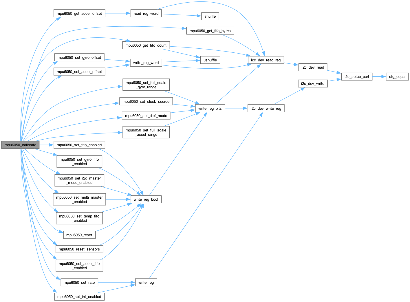
◆ mpu6050_calibrate()
| esp_err_t mpu6050_calibrate | ( | mpu6050_dev_t * | dev, |
| float * | accel_bias_res, | ||
| float * | gyro_bias_res ) |
Function which accumulates gyro and accelerometer data after device initialization.
It calculates the average of the at-rest readings and then loads the resulting offsets into accelerometer and gyro bias registers.
- Parameters
-
dev Device descriptor [out] accel_bias_res Acceleration bias resolution. [out] gyro_bias_res Rotation bias resolution.
- Returns
- ESP_OK on success
< Invalid argument
< esp_err_t value indicating success (no error)
< esp_err_t value indicating success (no error)
< esp_err_t value indicating success (no error)
< esp_err_t value indicating success (no error)
< esp_err_t value indicating success (no error)
< esp_err_t value indicating success (no error)
< esp_err_t value indicating success (no error)
< esp_err_t value indicating success (no error)
< esp_err_t value indicating success (no error)
< esp_err_t value indicating success (no error)
< esp_err_t value indicating success (no error)
< esp_err_t value indicating success (no error)
< esp_err_t value indicating success (no error)
< esp_err_t value indicating success (no error)
< esp_err_t value indicating success (no error)
< esp_err_t value indicating success (no error)
< esp_err_t value indicating success (no error)
< esp_err_t value indicating success (no error)
Configure FIFO to capture data for bias calculation.
< esp_err_t value indicating success (no error)
< esp_err_t value indicating success (no error)
< esp_err_t value indicating success (no error)
< esp_err_t value indicating success (no error)
< esp_err_t value indicating success (no error)
< esp_err_t value indicating success (no error)
< esp_err_t value indicating success (no error)
< esp_err_t value indicating success (no error)
< esp_err_t value indicating success (no error)
< esp_err_t value indicating success (no error)
< esp_err_t value indicating success (no error)
< esp_err_t value indicating success (no error)
< esp_err_t value indicating success (no error)
Construct the gyro biases for push to the hardware gyro bias registers, which are reset to zero upon device startup:
< esp_err_t value indicating success (no error)
< esp_err_t value indicating success (no error)
< esp_err_t value indicating success (no error)
Construct the accelerometer biases for push to the hardware accelerometer bias registers. These registers contain factory trim values which must be added to the calculated accelerometer biases; on boot up these registers will hold non-zero values. In addition, bit 0 of the lower byte must be preserved since it is used for temperature compensation calculations. Accelerometer bias registers expect bias input as 2048 LSB per g, so that the accelerometer biases calculated above must be divided by 8.
< esp_err_t value indicating success (no error)
< esp_err_t value indicating success (no error)
< esp_err_t value indicating success (no error)
Construct total accelerometer bias, including calculated average accelerometer bias from above (Subtract calculated averaged accelerometer bias scaled to 2048 LSB/g (16g full scale).
< esp_err_t value indicating success (no error)
< esp_err_t value indicating success (no error)
< esp_err_t value indicating success (no error)
< esp_err_t value indicating success (no error)
◆ mpu6050_free_desc()
| esp_err_t mpu6050_free_desc | ( | mpu6050_dev_t * | dev | ) |
Free device descriptor.
- Parameters
-
dev Device descriptor
- Returns
- ESP_OK on success
< Invalid argument

◆ mpu6050_get_accel_fifo_enabled()
| esp_err_t mpu6050_get_accel_fifo_enabled | ( | mpu6050_dev_t * | dev, |
| bool * | enabled ) |
Get accelerometer FIFO enabled value.
When set to 1, this bit enables ACCEL_XOUT_H, ACCEL_XOUT_L, ACCEL_YOUT_H, ACCEL_YOUT_L, ACCEL_ZOUT_H, and ACCEL_ZOUT_L (Registers 59 to 64) to be written into the FIFO buffer.
- Parameters
-
dev Device descriptor [out] enabled Gyroscope axis FIFO enabled value.
- Returns
- ESP_OK on success

◆ mpu6050_get_accel_offset()
| esp_err_t mpu6050_get_accel_offset | ( | mpu6050_dev_t * | dev, |
| mpu6050_axis_t | axis, | ||
| int16_t * | offset ) |
Get offset for accelerometer axis.
Undocumented register/feature
- Parameters
-
dev Device descriptor axis Accelerometer axis [out] offset Offset
- Returns
- ESP_OK on success
< Invalid argument


◆ mpu6050_get_accel_self_test()
| esp_err_t mpu6050_get_accel_self_test | ( | mpu6050_dev_t * | dev, |
| mpu6050_axis_t | axis, | ||
| bool * | enabled ) |
Get self-test enabled for accelerometer axis.
- Parameters
-
dev Device descriptor axis Accelerometer axis [out] enabled true if self-test enabled
- Returns
- ESP_OK on success
< Invalid argument

◆ mpu6050_get_accel_self_test_factory_trim()
| esp_err_t mpu6050_get_accel_self_test_factory_trim | ( | mpu6050_dev_t * | dev, |
| mpu6050_axis_t | axis, | ||
| uint8_t * | trim ) |
Get self-test factory trim value for accelerometer axis.
- Parameters
-
dev Device descriptor axis Accelerometer axis [out] trim Factory trim value.
- Returns
- ESP_OK on success
< Invalid argument
< esp_err_t value indicating success (no error)
< esp_err_t value indicating success (no error)
< esp_err_t value indicating success (no error)
< esp_err_t value indicating success (no error)
< esp_err_t value indicating success (no error)
< esp_err_t value indicating success (no error)
< esp_err_t value indicating success (no error)


◆ mpu6050_get_acceleration()
| esp_err_t mpu6050_get_acceleration | ( | mpu6050_dev_t * | dev, |
| mpu6050_acceleration_t * | accel ) |
Get 3-axis accelerometer readings.
These registers store the most recent accelerometer measurements. Accelerometer measurements are written to these registers at the Sample Rate as defined in Register 25.
The accelerometer measurement registers, along with the temperature measurement registers, gyroscope measurement registers, and external sensor data registers, are composed of two sets of registers: an internal register set and a user-facing read register set.
The data within the accelerometer sensors' internal register set is always updated at the Sample Rate. Meanwhile, the user-facing read register set duplicates the internal register set's data values whenever the serial interface is idle. This guarantees that a burst read of sensor registers will read measurements from the same sampling instant. Note that if burst reads are not used, the user is responsible for ensuring a set of single byte reads correspond to a single sampling instant by checking the Data Ready interrupt.
- Parameters
-
dev Device descriptor [out] accel Three-axis acceleration data, g.
- Returns
- ESP_OK on success
< Invalid argument
< esp_err_t value indicating success (no error)
< esp_err_t value indicating success (no error)

◆ mpu6050_get_acceleration_axis()
| esp_err_t mpu6050_get_acceleration_axis | ( | mpu6050_dev_t * | dev, |
| mpu6050_axis_t | axis, | ||
| float * | accel ) |
Get accelerometer reading on a single axis.
- Parameters
-
dev Device descriptor axis Accelerometer axis [out] accel Axis acceleration measurement, g
- Returns
- ESP_OK on success
< Invalid argument
< esp_err_t value indicating success (no error)
< esp_err_t value indicating success (no error)

◆ mpu6050_get_accelerometer_power_on_delay()
| esp_err_t mpu6050_get_accelerometer_power_on_delay | ( | mpu6050_dev_t * | dev, |
| uint8_t * | delay ) |
Get accelerometer power-on delay.
The accelerometer data path provides samples to the sensor registers, Motion detection, Zero Motion detection, and Free Fall detection modules. The signal path contains filters which must be flushed on wake-up with new samples before the detection modules begin operations. The default wake-up delay, of 4ms can be lengthened by up to 3ms. This additional delay is specified in ACCEL_ON_DELAY in units of 1 LSB = 1 ms. The user may select any value above zero unless instructed otherwise by InvenSense. Please refer to Section 8 of the MPU-6000/MPU-6050 Product Specification document for further information regarding the detection modules.
- Parameters
-
dev Device descriptor [out] delay Current accelerometer power-on delay.
- Returns
- ESP_OK on success

◆ mpu6050_get_aux_vddio_level()
| esp_err_t mpu6050_get_aux_vddio_level | ( | mpu6050_dev_t * | dev, |
| mpu6050_vddio_level_t * | level ) |
Get the auxiliary I2C supply voltage level.
When set to 1, the auxiliary I2C bus high logic level is VDD. When cleared to 0, the auxiliary I2C bus high logic level is VLOGIC. This does not apply to the MPU-6000, which does not have a VLOGIC pin.
- Parameters
-
dev Device descriptor [out] level I2C supply voltage level
- Returns
- ESP_OK on success

◆ mpu6050_get_clock_output_enabled()
| esp_err_t mpu6050_get_clock_output_enabled | ( | mpu6050_dev_t * | dev, |
| bool * | enabled ) |
Get reference clock output enabled status.
When this bit is equal to 1, a reference clock output is provided at the CLKOUT pin. When this bit is equal to 0, the clock output is disabled.
- Parameters
-
dev Device descriptor [out] enabled Current reference clock output enabled status.
- Returns
- ESP_OK on success

◆ mpu6050_get_clock_source()
| esp_err_t mpu6050_get_clock_source | ( | mpu6050_dev_t * | dev, |
| mpu6050_clock_source_t * | source ) |
Get clock source setting.
An internal 8MHz oscillator, gyroscope based clock, or external sources can be selected as the MPU-60X0 clock source. When the internal 8 MHz oscillator or an external source is chosen as the clock source, the MPU-60X0 can operate in low power modes with the gyroscopes disabled.
Upon power up, the MPU-60X0 clock source defaults to the internal oscillator. However, it is highly recommended that the device be configured to use one of the gyroscopes (or an external clock source) as the clock reference for improved stability.
- Parameters
-
dev Device descriptor [out] source Current clock source setting.
- Returns
- ESP_OK on success

◆ mpu6050_get_device_id()
| esp_err_t mpu6050_get_device_id | ( | mpu6050_dev_t * | dev, |
| uint8_t * | id ) |
Get the ID of the device.
Device identity is stored in the WHO_AM_I register. The device ID is 6 bits (Should be 0x34).
- Parameters
-
dev Device descriptor [out] id Device ID.
- Returns
- ESP_OK on success

◆ mpu6050_get_dhpf_mode()
| esp_err_t mpu6050_get_dhpf_mode | ( | mpu6050_dev_t * | dev, |
| mpu6050_dhpf_mode_t * | mode ) |
Get the high-pass filter configuration. The DHPF is a filter module in the path leading to motion detectors (Free Fall, Motion threshold, and Zero Motion). The high pass filter output is not available to the data registers.
The high pass filter has three modes:
Reset: The filter output settles to zero within one sample. This effectively disables the high pass filter. This mode may be toggled to quickly settle the filter.
On: The high pass filter will pass signals above the cut off frequency.
Hold: When triggered, the filter holds the present sample. The filter output will be the difference between the input sample and the held sample.
- Parameters
-
dev Device descriptor [out] mode Current high-pass filter configuration
- Returns
- ESP_OK on success

◆ mpu6050_get_dlpf_mode()
| esp_err_t mpu6050_get_dlpf_mode | ( | mpu6050_dev_t * | dev, |
| mpu6050_dlpf_mode_t * | mode ) |
Get digital low-pass filter configuration.
The DLPF_CFG parameter sets the digital low pass filter configuration. It also determines the internal sampling rate used by the device.
Note: The accelerometer output rate is 1kHz. This means that for a Sample Rate greater than 1kHz, the same accelerometer sample may be output to the FIFO, DMP, and sensor registers more than once.
- Parameters
-
dev Device descriptor [out] mode DLFP configuration.
- Returns
- ESP_OK on success

◆ mpu6050_get_external_frame_sync()
| esp_err_t mpu6050_get_external_frame_sync | ( | mpu6050_dev_t * | dev, |
| mpu6050_ext_sync_t * | sync ) |
Get external FSYNC configuration.
Configures the external Frame Synchronization (FSYNC) pin sampling. An external signal connected to the FSYNC pin can be sampled by configuring EXT_SYNC_SET. Signal changes to the FSYNC pin are latched so that short strobes may be captured. The latched FSYNC signal will be sampled at the Sampling Rate, as defined in register 25. After sampling, the latch will reset to the current FSYNC signal state. The sampled value will be reported in place of the least significant bit in a sensor data register determined by the value of EXT_SYNC_SET.
- Parameters
-
dev Device descriptor [out] sync FSYNC configuration value.
- Returns
- ESP_OK on success

◆ mpu6050_get_external_sensor_data()
| esp_err_t mpu6050_get_external_sensor_data | ( | mpu6050_dev_t * | dev, |
| int | position, | ||
| void * | buf, | ||
| size_t | length ) |
Read bytes from external sensor data register.
These registers store data read from external sensors by the Slave 0, 1, 2, and 3 on the auxiliary I2C interface. Data read by Slave 4 is stored in I2C_SLV4_DI (Register 53).
External sensor data is written to these registers at the Sample Rate as defined in Register 25. This access rate can be reduced by using the Slave Delay Enable registers (Register 103).
External sensor data registers, along with the gyroscope measurement registers, accelerometer measurement registers, and temperature measurement registers, are composed of two sets of registers: an internal register set and a user-facing read register set.
The data within the external sensors' internal register set is always updated at the Sample Rate (or the reduced access rate) whenever the serial interface is idle. This guarantees that a burst read of sensor registers will read measurements from the same sampling instant. Note that if burst reads are not used, the user is responsible for ensuring a set of single byte reads correspond to a single sampling instant by checking the Data Ready interrupt.
Data is placed in these external sensor data registers according to I2C_SLV0_CTRL, I2C_SLV1_CTRL, I2C_SLV2_CTRL, and I2C_SLV3_CTRL (Registers 39, 42, 45, and 48). When more than zero bytes are read (I2C_SLVx_LEN > 0) from an enabled slave (I2C_SLVx_EN = 1), the slave is read at the Sample Rate (as defined in Register 25) or delayed rate (if specified in Register 52 and 103). During each Sample cycle, slave reads are performed in order of Slave number. If all slaves are enabled with more than zero bytes to be read, the order will be Slave 0, followed by Slave 1, Slave 2, and Slave 3.
Each enabled slave will have EXT_SENS_DATA registers associated with it by number of bytes read (I2C_SLVx_LEN) in order of slave number, starting from EXT_SENS_DATA_00. Note that this means enabling or disabling a slave may change the higher numbered slaves' associated registers. Furthermore, if fewer total bytes are being read from the external sensors as a result of such a change, then the data remaining in the registers which no longer have an associated slave device (i.e. high numbered registers) will remain in these previously allocated registers unless reset.
If the sum of the read lengths of all SLVx transactions exceed the number of available EXT_SENS_DATA registers, the excess bytes will be dropped. There are 24 EXT_SENS_DATA registers and hence the total read lengths between all the slaves cannot be greater than 24 or some bytes will be lost.
Note: Slave 4's behavior is distinct from that of Slaves 0-3. For further information regarding the characteristics of Slave 4, please refer to Registers 49 to 53.
Suppose that Slave 0 is enabled with 4 bytes to be read (I2C_SLV0_EN = 1 and I2C_SLV0_LEN = 4) while Slave 1 is enabled with 2 bytes to be read so that I2C_SLV1_EN = 1 and I2C_SLV1_LEN = 2. In such a situation, EXT_SENS_DATA _00 through _03 will be associated with Slave 0, while EXT_SENS_DATA _04 and 05 will be associated with Slave 1. If Slave 2 is enabled as well, registers starting from EXT_SENS_DATA_06 will be allocated to Slave 2.
If Slave 2 is disabled while Slave 3 is enabled in this same situation, then registers starting from EXT_SENS_DATA_06 will be allocated to Slave 3 instead.
REGISTER ALLOCATION FOR DYNAMIC DISABLE VS. NORMAL DISABLE: If a slave is disabled at any time, the space initially allocated to the slave in the EXT_SENS_DATA register, will remain associated with that slave. This is to avoid dynamic adjustment of the register allocation.
The allocation of the EXT_SENS_DATA registers is recomputed only when (1) all slaves are disabled, or (2) the I2C_MST_RST bit is set (Register 106).
This above is also true if one of the slaves gets NACKed and stops functioning.
- Parameters
-
dev Device descriptor position Starting position (0-23). [out] buf Buffer to store data length Bytes to read
- Returns
- ESP_OK on success
< Invalid argument
< esp_err_t value indicating success (no error)
< esp_err_t value indicating success (no error)
< esp_err_t value indicating success (no error)
< esp_err_t value indicating success (no error)
< esp_err_t value indicating success (no error)

◆ mpu6050_get_external_shadow_delay_enabled()
| esp_err_t mpu6050_get_external_shadow_delay_enabled | ( | mpu6050_dev_t * | dev, |
| bool * | enabled ) |
Get external data shadow delay enabled status.
This register is used to specify the timing of external sensor data shadowing. When DELAY_ES_SHADOW is set to 1, shadowing of external sensor data is delayed until all data has been received.
- Parameters
-
dev Device descriptor [out] enabled External data shadow delay enabled status.
- Returns
- ESP_OK on success

◆ mpu6050_get_fifo_byte()
| esp_err_t mpu6050_get_fifo_byte | ( | mpu6050_dev_t * | dev, |
| uint8_t * | data ) |
Get byte from FIFO buffer.
This register is used to read and write data from the FIFO buffer. Data is written to the FIFO in order of register number (from lowest to highest). If all the FIFO enable flags (see below) are enabled and all External Sensor Data registers (Registers 73 to 96) are associated with a Slave device, the contents of registers 59 through 96 will be written in order at the Sample Rate.
The contents of the sensor data registers (Registers 59 to 96) are written into the FIFO buffer when their corresponding FIFO enable flags are set to 1 in FIFO_EN (Register 35). An additional flag for the sensor data registers associated with I2C Slave 3 can be found in I2C_MST_CTRL (Register 36).
If the FIFO buffer has overflowed, the status bit FIFO_OFLOW_INT is automatically set to 1. This bit is located in INT_STATUS (Register 58). When the FIFO buffer has overflowed, the oldest data will be lost and new data will be written to the FIFO.
If the FIFO buffer is empty, reading this register will return the last byte that was previously read from the FIFO until new data is available. The user should check FIFO_COUNT to ensure that the FIFO buffer is not read when empty.
- Parameters
-
dev Device descriptor [out] data Byte from FIFO buffer.
- Returns
- ESP_OK on success

◆ mpu6050_get_fifo_bytes()
| esp_err_t mpu6050_get_fifo_bytes | ( | mpu6050_dev_t * | dev, |
| uint8_t * | data, | ||
| size_t | length ) |
Get bytes from FIFO buffer.
- Parameters
-
dev Device descriptor [out] data Buffer to store read bytes length How many bytes to read
- Returns
- ESP_OK on success
< Invalid argument
< esp_err_t value indicating success (no error)
< esp_err_t value indicating success (no error)
< esp_err_t value indicating success (no error)
< esp_err_t value indicating success (no error)
< esp_err_t value indicating success (no error)


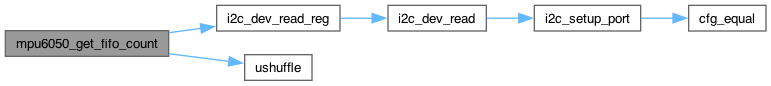
◆ mpu6050_get_fifo_count()
| esp_err_t mpu6050_get_fifo_count | ( | mpu6050_dev_t * | dev, |
| uint16_t * | count ) |
Get current FIFO buffer size.
This value indicates the number of bytes stored in the FIFO buffer. This number is in turn the number of bytes that can be read from the FIFO buffer and it is directly proportional to the number of samples available given the set of sensor data bound to be stored in the FIFO (Register 35 and 36).
- Parameters
-
dev Device descriptor [out] count Current FIFO buffer size.
- Returns
- ESP_OK on success
< Invalid argument
< esp_err_t value indicating success (no error)
< esp_err_t value indicating success (no error)
< esp_err_t value indicating success (no error)
< esp_err_t value indicating success (no error)
< esp_err_t value indicating success (no error)

◆ mpu6050_get_fifo_enabled()
| esp_err_t mpu6050_get_fifo_enabled | ( | mpu6050_dev_t * | dev, |
| bool * | enabled ) |
Get FIFO enabled status.
When this bit is set to 0, the FIFO buffer is disabled. The FIFO buffer cannot be written to or read from while disabled. The FIFO buffer's state does not change unless the MPU-60X0 is power cycled.
- Parameters
-
dev Device descriptor [out] enabled FIFO enabled status.
- Returns
- ESP_OK on success

◆ mpu6050_get_freefall_detection_counter_decrement()
| esp_err_t mpu6050_get_freefall_detection_counter_decrement | ( | mpu6050_dev_t * | dev, |
| uint8_t * | decrement ) |
Get Free Fall detection counter decrement configuration.
Detection is registered by the Free Fall detection module after accelerometer measurements meet their respective threshold conditions over a specified number of samples. When the threshold conditions are met, the corresponding detection counter increments by 1. The user may control the rate at which the detection counter decrements when the threshold condition is not met by configuring FF_COUNT. The decrement rate can be set according to the following table:
| FF_COUNT | Counter Decrement |
|---|---|
| 0 | Reset |
| 1 | 1 |
| 2 | 2 |
| 3 | 4 |
When FF_COUNT is configured to 0 (reset), any non-qualifying sample will reset the counter to 0. For further information on Free Fall detection, please refer to Registers 29 to 32.
- Parameters
-
dev Device descriptor [out] decrement Current decrement configuration.
- Returns
- ESP_OK on success

◆ mpu6050_get_freefall_detection_duration()
| esp_err_t mpu6050_get_freefall_detection_duration | ( | mpu6050_dev_t * | dev, |
| uint8_t * | duration_ms ) |
Get free-fall event duration threshold.
This register configures the duration_ms counter threshold for Free Fall event detection. The duration counter ticks at 1kHz, therefore FF_DUR has a unit of 1 LSB = 1 ms.
The Free Fall duration counter increments while the absolute value of the accelerometer measurements are each less than the detection threshold (Register 29). The Free Fall interrupt is triggered when the Free Fall duration_ms counter reaches the time specified in this register.
- Parameters
-
dev Device descriptor [out] duration_ms Current free-fall duration threshold value, ms
- Returns
- ESP_OK on success

◆ mpu6050_get_freefall_detection_threshold()
| esp_err_t mpu6050_get_freefall_detection_threshold | ( | mpu6050_dev_t * | dev, |
| uint8_t * | threshold ) |
Get free-fall event acceleration threshold.
This register configures the detection threshold for Free Fall event detection. The unit of FF_THR is 1LSB = 2mg. Free Fall is detected when the absolute value of the accelerometer measurements for the three axes are each less than the detection threshold. This condition increments the Free Fall duration counter (Register 30). The Free Fall interrupt is triggered when the Free Fall duration counter reaches the time specified in FF_DUR.
- Parameters
-
dev Device descriptor [out] threshold Current free-fall acceleration threshold value (LSB = 2mg)
- Returns
- ESP_OK on success

◆ mpu6050_get_fsync_interrupt_enabled()
| esp_err_t mpu6050_get_fsync_interrupt_enabled | ( | mpu6050_dev_t * | dev, |
| bool * | enabled ) |
Get FSYNC pin interrupt enabled setting.
- Parameters
-
dev Device descriptor [out] enabled FSYNC pin interrupt enabled setting
- Returns
- ESP_OK on success

◆ mpu6050_get_fsync_interrupt_level()
| esp_err_t mpu6050_get_fsync_interrupt_level | ( | mpu6050_dev_t * | dev, |
| mpu6050_int_level_t * | level ) |
Get FSYNC interrupt logic level.
- Parameters
-
dev Device descriptor [out] level Current FSYNC interrupt logic level.
- Returns
- ESP_OK on success

◆ mpu6050_get_full_scale_accel_range()
| esp_err_t mpu6050_get_full_scale_accel_range | ( | mpu6050_dev_t * | dev, |
| mpu6050_accel_range_t * | range ) |
Get full-scale accelerometer range.
The FS_SEL parameter allows dev the full-scale range of the accelerometer sensors.
- Parameters
-
dev Device descriptor [out] range Current full-scale accelerometer range setting
- Returns
- ESP_OK on success
< esp_err_t value indicating success (no error)

◆ mpu6050_get_full_scale_gyro_range()
| esp_err_t mpu6050_get_full_scale_gyro_range | ( | mpu6050_dev_t * | dev, |
| mpu6050_gyro_range_t * | gyro_range ) |
Get full-scale gyroscope range.
The FS_SEL parameter allows setting the full-scale range of the gyro sensors.
- Parameters
-
dev Device descriptor [out] gyro_range full-scale gyroscope range setting.
- Returns
- ESP_OK on success
< esp_err_t value indicating success (no error)

◆ mpu6050_get_gyro_fifo_enabled()
| esp_err_t mpu6050_get_gyro_fifo_enabled | ( | mpu6050_dev_t * | dev, |
| mpu6050_axis_t | axis, | ||
| bool * | enabled ) |
Get gyroscope axis FIFO enabled value.
- Parameters
-
dev Device descriptor axis Gyroscope axis [out] enabled Gyroscope axis FIFO enabled value.
- Returns
- ESP_OK on success
< Invalid argument

◆ mpu6050_get_gyro_offset()
| esp_err_t mpu6050_get_gyro_offset | ( | mpu6050_dev_t * | dev, |
| mpu6050_axis_t | axis, | ||
| int16_t * | offset ) |
Get offset for gyroscope axis.
Undocumented register/feature
- Parameters
-
dev Device descriptor axis Gyroscope axis [out] offset Offset
- Returns
- ESP_OK on success
< Invalid argument

◆ mpu6050_get_gyro_self_test_factory_trim()
| esp_err_t mpu6050_get_gyro_self_test_factory_trim | ( | mpu6050_dev_t * | dev, |
| mpu6050_axis_t | axis, | ||
| uint8_t * | trim ) |
Get self-test factory trim value for gyroscope axis.
- Parameters
-
dev Device descriptor axis Gyroscope axis [out] trim Factory trim value.
- Returns
- ESP_OK on success
< Invalid argument
< esp_err_t value indicating success (no error)
< esp_err_t value indicating success (no error)


◆ mpu6050_get_i2c_bypass_enabled()
| esp_err_t mpu6050_get_i2c_bypass_enabled | ( | mpu6050_dev_t * | dev, |
| bool * | enabled ) |
Get I2C bypass enabled status.
When this bit is equal to 1 and I2C master is disabled, the host application processor will be able to directly access the auxiliary I2C bus of the MPU-60X0. When this bit is equal to 0, the host application processor will not be able to directly access the auxiliary I2C bus of the MPU-60X0 regardless of the state of I2C master.
- Parameters
-
dev Device descriptor [out] enabled Current I2C bypass enabled status.
- Returns
- ESP_OK on success

◆ mpu6050_get_i2c_master_mode_enabled()
| esp_err_t mpu6050_get_i2c_master_mode_enabled | ( | mpu6050_dev_t * | dev, |
| bool * | enabled ) |
Get I2C Master Mode enabled status.
When this mode is enabled, the MPU-60X0 acts as the I2C Master to the external sensor slave devices on the auxiliary I2C bus. When this bit is cleared to 0, the auxiliary I2C bus lines (AUX_DA and AUX_CL) are logically driven by the primary I2C bus (SDA and SCL). This is a precondition to enabling Bypass Mode.
- Parameters
-
dev Device descriptor [out] enabled I2C Master Mode enabled status.
- Returns
- ESP_OK on success

◆ mpu6050_get_int_enabled()
| esp_err_t mpu6050_get_int_enabled | ( | mpu6050_dev_t * | dev, |
| uint8_t * | ints ) |
Get full interrupt enabled status.
Full register byte for all interrupts, for quick reading. Each bit will be set 0 for disabled, 1 for enabled.
- Parameters
-
dev Device descriptor [out] ints Combination of mpu6050_int_source_t flags
- Returns
- ESP_OK on success

◆ mpu6050_get_int_status()
| esp_err_t mpu6050_get_int_status | ( | mpu6050_dev_t * | dev, |
| uint8_t * | ints ) |
Get full set of interrupt status bits.
These bits clear to 0 after the register has been read. Very useful for getting multiple INT statuses, since each single bit read clears all of them because it has to read the whole byte.
- Parameters
-
dev Device descriptor [out] ints Combination of mpu6050_int_source_t flags
- Returns
- ESP_OK on success

◆ mpu6050_get_interrupt_drive()
| esp_err_t mpu6050_get_interrupt_drive | ( | mpu6050_dev_t * | dev, |
| mpu6050_int_drive_t * | drive ) |
Get interrupt drive mode.
- Parameters
-
dev Device descriptor [out] drive Current interrupt drive mode
- Returns
- ESP_OK on success

◆ mpu6050_get_interrupt_latch()
| esp_err_t mpu6050_get_interrupt_latch | ( | mpu6050_dev_t * | dev, |
| mpu6050_int_latch_t * | latch ) |
Get interrupt latch mode.
- Parameters
-
dev Device descriptor [out] latch Current latch mode
- Returns
- ESP_OK on success

◆ mpu6050_get_interrupt_latch_clear()
| esp_err_t mpu6050_get_interrupt_latch_clear | ( | mpu6050_dev_t * | dev, |
| bool * | clear ) |
Get interrupt latch clear mode.
- Parameters
-
dev Device descriptor [out] clear Current latch clear mode (false = status-read-only, true = any-register-read).
- Returns
- ESP_OK on success

◆ mpu6050_get_interrupt_mode()
| esp_err_t mpu6050_get_interrupt_mode | ( | mpu6050_dev_t * | dev, |
| mpu6050_int_level_t * | mode ) |
Get interrupt logic level mode.
- Parameters
-
dev Device descriptor [out] mode Interrupt logic level mode
- Returns
- ESP_OK on success

◆ mpu6050_get_lost_arbitration()
| esp_err_t mpu6050_get_lost_arbitration | ( | mpu6050_dev_t * | dev, |
| bool * | lost ) |
Get master arbitration lost status.
This bit automatically sets to 1 when the I2C Master has lost arbitration of the auxiliary I2C bus (an error condition). This triggers an interrupt if the I2C_MST_INT_EN bit in the INT_ENABLE register (Register 56) is asserted.
- Parameters
-
dev Device descriptor [out] lost Master arbitration lost status
- Returns
- ESP_OK on success

◆ mpu6050_get_master_clock_speed()
| esp_err_t mpu6050_get_master_clock_speed | ( | mpu6050_dev_t * | dev, |
| mpu6050_i2c_master_clock_t * | clk_spd ) |
Get I2C master clock speed.
I2C_MST_CLK is a 4 bit unsigned value which configures a divider on the MPU-60X0 internal 8MHz clock.
- Parameters
-
dev Device descriptor [out] clk_spd Current I2C master clock speed.
- Returns
- ESP_OK on success

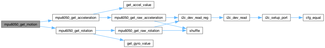
◆ mpu6050_get_motion()
| esp_err_t mpu6050_get_motion | ( | mpu6050_dev_t * | dev, |
| mpu6050_acceleration_t * | data_accel, | ||
| mpu6050_rotation_t * | data_gyro ) |
Get raw 6-axis motion sensor readings (accel/gyro).
Retrieves all currently available motion sensor values.
- Parameters
-
dev Device descriptor [out] data_accel acceleration struct. [out] data_gyro rotation struct.
- Returns
- ESP_OK on success
< esp_err_t value indicating success (no error)
< esp_err_t value indicating success (no error)
< esp_err_t value indicating success (no error)

◆ mpu6050_get_motion_detection_counter_decrement()
| esp_err_t mpu6050_get_motion_detection_counter_decrement | ( | mpu6050_dev_t * | dev, |
| uint8_t * | decrement ) |
Get Motion detection counter decrement configuration.
Detection is registered by the Motion detection module after accelerometer measurements meet their respective threshold conditions over a specified number of samples. When the threshold conditions are met, the corresponding detection counter increments by 1. The user may control the rate at which the detection counter decrements when the threshold condition is not met by configuring MOT_COUNT. The decrement rate can be set according to the following table:
| MOT_COUNT | Counter Decrement |
|---|---|
| 0 | Reset |
| 1 | 1 |
| 2 | 2 |
| 3 | 4 |
When MOT_COUNT is configured to 0 (reset), any non-qualifying sample will reset the counter to 0.
- Parameters
-
dev Device descriptor [out] decrement New decrement configuration value.
- Returns
- ESP_OK on success

◆ mpu6050_get_motion_detection_duration()
| esp_err_t mpu6050_get_motion_detection_duration | ( | mpu6050_dev_t * | dev, |
| uint8_t * | duration ) |
Get motion detection event duration threshold.
This register configures the duration counter threshold for Motion interrupt generation. The duration counter ticks at 1 kHz, therefore MOT_DUR has a unit of 1LSB = 1ms. The Motion detection duration counter increments when the absolute value of any of the accelerometer measurements exceeds the Motion detection threshold (Register 31). The Motion detection interrupt is triggered when the Motion detection counter reaches the time count specified in this register.
- Parameters
-
dev Device descriptor [out] duration Current motion detection duration threshold value, ms
- Returns
- ESP_OK on success

◆ mpu6050_get_motion_detection_threshold()
| esp_err_t mpu6050_get_motion_detection_threshold | ( | mpu6050_dev_t * | dev, |
| uint8_t * | threshold ) |
Get motion detection event acceleration threshold.
This register configures the detection threshold for Motion interrupt generation. The unit of MOT_THR is 1LSB = 2mg. Motion is detected when the absolute value of any of the accelerometer measurements exceeds this Motion detection threshold. This condition increments the Motion detection duration counter (Register 32). The Motion detection interrupt is triggered when the Motion Detection counter reaches the time count specified in MOT_DUR (Register 32).
The Motion interrupt will indicate the axis and polarity of detected motion in MOT_DETECT_STATUS (Register 97).
- Parameters
-
dev Device descriptor [out] threshold Current motion detection acceleration threshold value (LSB = 2mg)
- Returns
- ESP_OK on success

◆ mpu6050_get_motion_status()
| esp_err_t mpu6050_get_motion_status | ( | mpu6050_dev_t * | dev, |
| uint8_t * | status ) |
Get full motion detection status register content (all bits).
- Parameters
-
dev Device descriptor [out] status Motion detection status byte, combination of mpu6050_motion_det_flags_t items
- Returns
- ESP_OK on success

◆ mpu6050_get_multi_master_enabled()
| esp_err_t mpu6050_get_multi_master_enabled | ( | mpu6050_dev_t * | dev, |
| bool * | enabled ) |
Get multi-master enabled value.
Multi-master capability allows multiple I2C masters to operate on the same bus. In circuits where multi-master capability is required, set MULT_MST_EN to 1. This will increase current drawn by approximately 30uA.
In circuits where multi-master capability is required, the state of the I2C bus must always be monitored by each separate I2C Master. Before an I2C Master can assume arbitration of the bus, it must first confirm that no other I2C Master has arbitration of the bus. When MULT_MST_EN is set to 1, the MPU-60X0's bus arbitration detection logic is turned on, enabling it to detect when the bus is available.
- Parameters
-
dev Device descriptor [out] enabled Multi-master enabled value.
- Returns
- ESP_OK on success

◆ mpu6050_get_passthrough_status()
| esp_err_t mpu6050_get_passthrough_status | ( | mpu6050_dev_t * | dev, |
| bool * | enabled ) |
Get FSYNC interrupt status.
This bit reflects the status of the FSYNC interrupt from an external device into the MPU-60X0. This is used as a way to pass an external interrupt through the MPU-60X0 to the host application processor. When set to 1, .
- Parameters
-
dev Device descriptor [out] enabled FSYNC interrupt status
- Returns
- ESP_OK on success

◆ mpu6050_get_rate()
| esp_err_t mpu6050_get_rate | ( | mpu6050_dev_t * | dev, |
| uint8_t * | rate ) |
Get gyroscope output rate divider.
The sensor register output, FIFO output, DMP sampling, Motion Detection, Zero Motion Detection and Free Fall Detection are all based on the Sample Rate. The Sample Rate is generated by dividing the gyroscope output rate by SMPLRT_DIV:
Sample Rate = Gyroscope Output Rate / (1 + SMPLRT_DIV)
Where Gyroscope Output Rate = 8kHz when the DLPF is disabled (DLPF_CFG = 0 or 7), and 1kHz when the DLPF is enabled.
Note: The accelerometer output rate is 1kHz. This means that for a Sample Rate greater than 1kHz, the same accelerometer sample may be output to the FIFO, DMP, and sensor registers more than once.
- Parameters
-
dev Device descriptor [out] rate accelerometer sample rate
- Returns
- ESP_OK on success

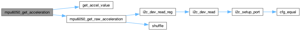
◆ mpu6050_get_raw_acceleration()
| esp_err_t mpu6050_get_raw_acceleration | ( | mpu6050_dev_t * | dev, |
| mpu6050_raw_acceleration_t * | raw_accel ) |
Get raw 3-axis accelerometer readings.
- Parameters
-
dev Device descriptor [out] raw_accel Raw acceleration data.
- Returns
- ESP_OK on success
< Invalid argument
< esp_err_t value indicating success (no error)
< esp_err_t value indicating success (no error)
< esp_err_t value indicating success (no error)
< esp_err_t value indicating success (no error)
< esp_err_t value indicating success (no error)

◆ mpu6050_get_raw_acceleration_axis()
| esp_err_t mpu6050_get_raw_acceleration_axis | ( | mpu6050_dev_t * | dev, |
| mpu6050_axis_t | axis, | ||
| int16_t * | raw_accel ) |
Get raw accelerometer reading on a single axis.
- Parameters
-
dev Device descriptor axis Accelerometer axis [out] raw_accel Raw axis acceleration measurement
- Returns
- ESP_OK on success
< Invalid argument


◆ mpu6050_get_raw_rotation()
| esp_err_t mpu6050_get_raw_rotation | ( | mpu6050_dev_t * | dev, |
| mpu6050_raw_rotation_t * | raw_gyro ) |
Get raw 3-axis gyroscope readings.
- Parameters
-
dev Device descriptor [out] raw_gyro Raw rotation data.
- Returns
- ESP_OK on success
< Invalid argument
< esp_err_t value indicating success (no error)
< esp_err_t value indicating success (no error)
< esp_err_t value indicating success (no error)
< esp_err_t value indicating success (no error)
< esp_err_t value indicating success (no error)

◆ mpu6050_get_raw_rotation_axis()
| esp_err_t mpu6050_get_raw_rotation_axis | ( | mpu6050_dev_t * | dev, |
| mpu6050_axis_t | axis, | ||
| int16_t * | raw_gyro ) |
Get raw gyroscope reading on a single axis.
- Parameters
-
dev Device descriptor axis Gyroscope axis [out] raw_gyro Raw axis rotation measurement
- Returns
- ESP_OK on success
< Invalid argument


◆ mpu6050_get_rotation()
| esp_err_t mpu6050_get_rotation | ( | mpu6050_dev_t * | dev, |
| mpu6050_rotation_t * | gyro ) |
Get 3-axis gyroscope readings.
These gyroscope measurement registers, along with the accelerometer measurement registers, temperature measurement registers, and external sensor data registers, are composed of two sets of registers: an internal register set and a user-facing read register set. The data within the gyroscope sensors' internal register set is always updated at the Sample Rate. Meanwhile, the user-facing read register set duplicates the internal register set's data values whenever the serial interface is idle. This guarantees that a burst read of sensor registers will read measurements from the same sampling instant. Note that if burst reads are not used, the user is responsible for ensuring a set of single byte reads correspond to a single sampling instant by checking the Data Ready interrupt.
- Parameters
-
dev Device descriptor [out] gyro Rotation data, °/s
- Returns
- ESP_OK on success
< Invalid argument
< esp_err_t value indicating success (no error)
< esp_err_t value indicating success (no error)

◆ mpu6050_get_rotation_axis()
| esp_err_t mpu6050_get_rotation_axis | ( | mpu6050_dev_t * | dev, |
| mpu6050_axis_t | axis, | ||
| float * | gyro ) |
Get gyroscope reading on a single axis.
- Parameters
-
dev Device descriptor axis Gyroscope axis [out] gyro Axis rotation measurement, °/s
- Returns
- ESP_OK on success
< Invalid argument
< esp_err_t value indicating success (no error)
< esp_err_t value indicating success (no error)

◆ mpu6050_get_slave_4_input_byte()
| esp_err_t mpu6050_get_slave_4_input_byte | ( | mpu6050_dev_t * | dev, |
| uint8_t * | byte ) |
Get last available byte read from Slave 4.
This register stores the data read from Slave 4. This field is populated after a read transaction.
- Parameters
-
dev Device descriptor [out] byte Last available byte read from to Slave 4.
- Returns
- ESP_OK on success

◆ mpu6050_get_slave_4_interrupt_enabled()
| esp_err_t mpu6050_get_slave_4_interrupt_enabled | ( | mpu6050_dev_t * | dev, |
| bool * | enabled ) |
Get the enabled value for Slave 4 transaction interrupts.
When set to 1, this bit enables the generation of an interrupt signal upon completion of a Slave 4 transaction. When cleared to 0, this bit disables the generation of an interrupt signal upon completion of a Slave 4 transaction. The interrupt status can be observed in Register 54.
- Parameters
-
dev Device descriptor [out] enabled Enabled value for Slave 4 transaction interrupts.
- Returns
- ESP_OK on success

◆ mpu6050_get_slave_4_is_done()
| esp_err_t mpu6050_get_slave_4_is_done | ( | mpu6050_dev_t * | dev, |
| bool * | enabled ) |
Get Slave 4 transaction done status.
Automatically sets to 1 when a Slave 4 transaction has completed. This triggers an interrupt if the I2C_MST_INT_EN bit in the INT_ENABLE register (Register 56) is asserted and if the SLV_4_DONE_INT bit is asserted in the I2C_SLV4_CTRL register (Register 52).
- Parameters
-
dev Device descriptor [out] enabled Slave 4 transaction done status
- Returns
- ESP_OK on success

◆ mpu6050_get_slave_4_master_delay()
| esp_err_t mpu6050_get_slave_4_master_delay | ( | mpu6050_dev_t * | dev, |
| uint8_t * | delay ) |
Get Slave 4 master delay value.
This configures the reduced access rate of I2C slaves relative to the Sample Rate. When a slave's access rate is decreased relative to the Sample Rate, the slave is accessed every:
1 / (1 + I2C_MST_DLY) samples
This base Sample Rate in turn is determined by SMPLRT_DIV (Register 25) and DLPF_CFG (Register 26). Whether a slave's access rate is reduced relative to the Sample Rate is determined by I2C_MST_DELAY_CTRL (Register 103).
- Parameters
-
dev Device descriptor [out] delay Current Slave 4 master delay value.
- Returns
- ESP_OK on success

◆ mpu6050_get_slave_address()
| esp_err_t mpu6050_get_slave_address | ( | mpu6050_dev_t * | dev, |
| mpu6050_slave_t | num, | ||
| uint8_t * | addr ) |
Get the I2C address of the specified slave.
Note that Bit 7 (MSB) controls read/write mode. If Bit 7 is set, it's a read operation, and if it is cleared, then it's a write operation. The remaining bits (6-0) are the 7-bit device address of the slave device.
In read mode, the result of the read is placed in the lowest available EXT_SENS_DATA register. For further information regarding the allocation of read results, please refer to the EXT_SENS_DATA register description (Registers 73 - 96).
The MPU-6050 supports a total of five slaves, but Slave 4 has unique characteristics, and so it has its own functions (getSlave4* and setSlave4*).
I2C data transactions are performed at the Sample Rate, as defined in Register 25. The user is responsible for ensuring that I2C data transactions to and from each enabled Slave can be completed within a single period of the Sample Rate.
The I2C slave access rate can be reduced relative to the Sample Rate. This reduced access rate is determined by I2C_MST_DLY (Register 52). Whether a slave's access rate is reduced relative to the Sample Rate is determined by I2C_MST_DELAY_CTRL (Register 103).
The processing order for the slaves is fixed. The sequence followed for processing the slaves is Slave 0, Slave 1, Slave 2, Slave 3 and Slave 4. If a particular Slave is disabled it will be skipped.
Each slave can either be accessed at the sample rate or at a reduced sample rate. In a case where some slaves are accessed at the Sample Rate and some slaves are accessed at the reduced rate, the sequence of accessing the slaves (Slave 0 to Slave 4) is still followed. However, the reduced rate slaves will be skipped if their access rate dictates that they should not be accessed during that particular cycle. For further information regarding the reduced access rate, please refer to Register 52. Whether a slave is accessed at the Sample Rate or at the reduced rate is determined by the Delay Enable bits in Register 103.
- Parameters
-
dev Device descriptor num Slave number (0-4). [out] addr Current address for specified slave.
- Returns
- ESP_OK on success
< Invalid argument

◆ mpu6050_get_slave_data_length()
| esp_err_t mpu6050_get_slave_data_length | ( | mpu6050_dev_t * | dev, |
| mpu6050_slave_t | num, | ||
| uint8_t * | length ) |
Get number of bytes to read for the specified slave.
Specifies the number of bytes transferred to and from Slave 0. Clearing this bit to 0 is equivalent to disabling the register by writing 0 to I2C_SLV0_EN.
- Parameters
-
dev Device descriptor num Slave number (0-4). [out] length Number of bytes to read for specified slave.
- Returns
- ESP_OK on success
< Invalid argument

◆ mpu6050_get_slave_delay_enabled()
| esp_err_t mpu6050_get_slave_delay_enabled | ( | mpu6050_dev_t * | dev, |
| mpu6050_slave_t | num, | ||
| bool * | enabled ) |
Get slave delay enabled status.
When a particular slave delay is enabled, the rate of access for the that slave device is reduced. When a slave's access rate is decreased relative to the Sample Rate, the slave is accessed every:
1 / (1 + I2C_MST_DLY) Samples
This base Sample Rate in turn is determined by SMPLRT_DIV (Register * 25) and DLPF_CFG (Register 26).
For further information regarding I2C_MST_DLY, please refer to register 52. For further information regarding the Sample Rate, please refer to register 25.
- Parameters
-
dev Device descriptor num Slave number (0-4). [out] enabled Slave delay enabled status.
- Returns
- ESP_OK on success
< Invalid argument

◆ mpu6050_get_slave_enabled()
| esp_err_t mpu6050_get_slave_enabled | ( | mpu6050_dev_t * | dev, |
| mpu6050_slave_t | num, | ||
| bool * | enabled ) |
Get the enabled value for the specified slave.
- Parameters
-
dev Device descriptor num Slave number (0-4). [out] enabled Enabled value for specified slave.
- Returns
- ESP_OK on success
< Invalid argument

◆ mpu6050_get_slave_fifo_enabled()
| esp_err_t mpu6050_get_slave_fifo_enabled | ( | mpu6050_dev_t * | dev, |
| mpu6050_slave_t | num, | ||
| bool * | enabled ) |
Get Slave FIFO enabled value.
When set to 1, this bit enables EXT_SENS_DATA registers (Registers 73 to 96) associated with Slave to be written into the FIFO buffer.
- Parameters
-
dev Device descriptor num Slave number (0-3) [out] enabled Slave FIFO enabled value.
- Returns
- ESP_OK on success
< Invalid argument

◆ mpu6050_get_slave_nack()
| esp_err_t mpu6050_get_slave_nack | ( | mpu6050_dev_t * | dev, |
| mpu6050_slave_t | num, | ||
| bool * | nack ) |
Get Slave NACK status.
This bit automatically sets to 1 when the I2C Master receives a NACK in a transaction with Slave 4. This triggers an interrupt if the I2C_MST_INT_EN bit in the INT_ENABLE register (Register 56) is asserted.
- Parameters
-
dev Device descriptor num Slave number (0-4). [out] nack Slave NACK status.
- Returns
- ESP_OK on success
< Invalid argument

◆ mpu6050_get_slave_read_write_transition_enabled()
| esp_err_t mpu6050_get_slave_read_write_transition_enabled | ( | mpu6050_dev_t * | dev, |
| bool * | enabled ) |
Get slave read/write transition enabled value.
The I2C_MST_P_NSR bit configures the I2C Master's transition from one slave read to the next slave read. If the bit equals 0, there will be a restart between reads. If the bit equals 1, there will be a stop followed by a start of the following read. When a write transaction follows a read transaction, the stop followed by a start of the successive write will be always used.
- Parameters
-
dev Device descriptor [out] enabled Slave read/write transition enabled value
- Returns
- ESP_OK on success

◆ mpu6050_get_slave_register()
| esp_err_t mpu6050_get_slave_register | ( | mpu6050_dev_t * | dev, |
| mpu6050_slave_t | num, | ||
| uint8_t * | reg ) |
Get the active internal register for the specified slave.
Read/write operations for this slave will be done to whatever internal register address is stored in this MPU register.
The MPU-6050 supports a total of five slaves, but Slave 4 has unique characteristics, and so it has its own functions.
- Parameters
-
dev Device descriptor num Slave number (0-4). [out] reg Current active register for specified slave.
- Returns
- ESP_OK on success
< Invalid argument

◆ mpu6050_get_slave_word_byte_swap()
| esp_err_t mpu6050_get_slave_word_byte_swap | ( | mpu6050_dev_t * | dev, |
| mpu6050_slave_t | num, | ||
| bool * | enabled ) |
Get word pair byte-swapping enabled for the specified slave.
When set to 1, this bit enables byte swapping. When byte swapping is enabled, the high and low bytes of a word pair are swapped. Please refer to I2C_SLV0_GRP for the pairing convention of the word pairs. When cleared to 0, bytes transferred to and from Slave will be written to EXT_SENS_DATA registers in the order they were transferred.
- Parameters
-
dev Device descriptor num Slave number (0-4). [out] enabled Word pair byte-swapping enabled value for specified slave.
- Returns
- ESP_OK on success
< Invalid argument

◆ mpu6050_get_slave_word_group_offset()
| esp_err_t mpu6050_get_slave_word_group_offset | ( | mpu6050_dev_t * | dev, |
| mpu6050_slave_t | num, | ||
| bool * | enabled ) |
Get word pair grouping order offset for the specified slave.
This sets specifies the grouping order of word pairs received from registers. When cleared to 0, bytes from register addresses 0 and 1, 2 and 3, etc (even, then odd register addresses) are paired to form a word. When set to 1, bytes from register addresses are paired 1 and 2, 3 and 4, etc. (odd, then even register addresses) are paired to form a word.
- Parameters
-
dev Device descriptor num Slave number (0-4). [out] enabled Word pair grouping order offset for specified slave.
- Returns
- ESP_OK on success
< Invalid argument

◆ mpu6050_get_slave_write_mode()
| esp_err_t mpu6050_get_slave_write_mode | ( | mpu6050_dev_t * | dev, |
| mpu6050_slave_t | num, | ||
| bool * | mode ) |
Get write mode for the specified slave.
When set to 1, the transaction will read or write data only. When cleared to 0, the transaction will write a register address prior to reading or writing data. This should equal 0 when specifying the register address within the Slave device to/from which the ensuing data transaction will take place.
- Parameters
-
dev Device descriptor num Slave number (0-4). [out] mode Write mode: false - register address + data, true - data only
- Returns
- ESP_OK on success
< Invalid argument

◆ mpu6050_get_sleep_enabled()
| esp_err_t mpu6050_get_sleep_enabled | ( | mpu6050_dev_t * | dev, |
| bool * | enabled ) |
Get sleep mode status.
The SLEEP bit in the register puts the device into very low power sleep mode. In this mode, only the serial interface and internal registers remain active, allowing for a very low standby current. Clearing this bit puts the device back into normal mode. To save power, the individual standby selections for each of the gyros should be used if any gyro axis is not used by the application.
- Parameters
-
dev Device descriptor [out] enabled Sleep mode enabled status.
- Returns
- ESP_OK on success

◆ mpu6050_get_standby_accel_enabled()
| esp_err_t mpu6050_get_standby_accel_enabled | ( | mpu6050_dev_t * | dev, |
| mpu6050_axis_t | axis, | ||
| bool * | enabled ) |
Get accelerometer axis standby enabled status.
If enabled, the axis will not gather or report data (or use power).
- Parameters
-
dev Device descriptor axis Accelerometer axis. [out] enabled Accelerometer axis standby enabled status.
- Returns
- ESP_OK on success
< Invalid argument

◆ mpu6050_get_standby_gyro_enabled()
| esp_err_t mpu6050_get_standby_gyro_enabled | ( | mpu6050_dev_t * | dev, |
| mpu6050_axis_t | axis, | ||
| bool * | enabled ) |
Get gyroscope axis standby enabled status.
If enabled, the axis will not gather or report data (or use power).
- Parameters
-
dev Device descriptor axis Gyroscope axis. [out] enabled Gyroscope axis standby enabled status.
- Returns
- ESP_OK on success
< Invalid argument

◆ mpu6050_get_temp_fifo_enabled()
| esp_err_t mpu6050_get_temp_fifo_enabled | ( | mpu6050_dev_t * | dev, |
| bool * | enabled ) |
Get temperature FIFO enabled value.
When set to 1, this bit enables TEMP_OUT_H and TEMP_OUT_L (Registers 65 and 66) to be written into the FIFO buffer.
- Parameters
-
dev Device descriptor [out] enabled true if temperature FIFO is enabled
- Returns
- ESP_OK on success

◆ mpu6050_get_temp_sensor_enabled()
| esp_err_t mpu6050_get_temp_sensor_enabled | ( | mpu6050_dev_t * | dev, |
| bool * | enabled ) |
Get temperature sensor enabled status.
Control the usage of the internal temperature sensor.
Note: this register stores the disabled value, but for consistency with the rest of the code, the function is named and used with standard true/false values to indicate whether the sensor is enabled or disabled, respectively.
- Parameters
-
dev Device descriptor [out] enabled Temperature sensor enabled status.
- Returns
- ESP_OK on success
< esp_err_t value indicating success (no error)
< esp_err_t value indicating success (no error)

◆ mpu6050_get_temperature()
| esp_err_t mpu6050_get_temperature | ( | mpu6050_dev_t * | dev, |
| float * | temp ) |
Get current internal temperature.
- Parameters
-
dev Device descriptor [out] temp Internal temperature, °C
- Returns
- ESP_OK on success
< Invalid argument
< esp_err_t value indicating success (no error)
< esp_err_t value indicating success (no error)

◆ mpu6050_get_wait_for_external_sensor_enabled()
| esp_err_t mpu6050_get_wait_for_external_sensor_enabled | ( | mpu6050_dev_t * | dev, |
| bool * | enabled ) |
Get wait-for-external-sensor-data enabled value.
When the WAIT_FOR_ES bit is set to 1, the Data Ready interrupt will be delayed until External Sensor data from the Slave Devices are loaded into the EXT_SENS_DATA registers. This is used to ensure that both the internal sensor data (i.e. from gyro and accel) and external sensor data have been loaded to their respective data registers (i.e. the data is synced) when the Data Ready interrupt is triggered.
- Parameters
-
dev Device descriptor [out] enabled Wait-for-external-sensor-data enabled value.
- Returns
- ESP_OK on success

◆ mpu6050_get_wake_cycle_enabled()
| esp_err_t mpu6050_get_wake_cycle_enabled | ( | mpu6050_dev_t * | dev, |
| bool * | enabled ) |
Get wake cycle enabled status.
When this bit is set to 1 and SLEEP is disabled, the MPU-60X0 will cycle between sleep mode and waking up to take a single sample of data from active sensors at a rate determined by LP_WAKE_CTRL (Register 108).
- Parameters
-
dev Device descriptor [out] enabled Wake cycle enabled status.
- Returns
- ESP_OK on success

◆ mpu6050_get_wake_frequency()
| esp_err_t mpu6050_get_wake_frequency | ( | mpu6050_dev_t * | dev, |
| mpu6050_wake_freq_t * | frequency ) |
Get wake frequency in Accel-Only Low Power Mode.
The MPU-60X0 can be put into Accelerometer Only Low Power Mode by setting PWRSEL to 1 in the Power Management 1 register (Register 107). In this mode, the device will power off all devices except for the primary I2C interface, waking only the accelerometer at fixed intervals to take a single measurement.
For further information regarding the MPU-60X0's power modes, please refer to Register 107.
- Parameters
-
dev Device descriptor [out] frequency Current wake frequency.
- Returns
- ESP_OK on success

◆ mpu6050_get_zero_motion_detection_duration()
| esp_err_t mpu6050_get_zero_motion_detection_duration | ( | mpu6050_dev_t * | dev, |
| uint8_t * | duration ) |
Get zero motion detection event duration threshold.
This register configures the duration counter threshold for Zero Motion interrupt generation. The duration counter ticks at 16 Hz, therefore ZRMOT_DUR has a unit of 1 LSB = 64 ms. The Zero Motion duration counter increments while the absolute value of the accelerometer measurements are each less than the detection threshold (Register 33). The Zero Motion interrupt is triggered when the Zero Motion duration counter reaches the time count specified in this register.
- Parameters
-
dev Device descriptor [out] duration Current zero motion detection duration threshold value (LSB = 64ms)
- Returns
- ESP_OK on success

◆ mpu6050_get_zero_motion_detection_threshold()
| esp_err_t mpu6050_get_zero_motion_detection_threshold | ( | mpu6050_dev_t * | dev, |
| uint8_t * | threshold ) |
Get zero motion detection event acceleration threshold.
This register configures the detection threshold for Zero Motion interrupt generation. The unit of ZRMOT_THR is 1LSB = 2mg. Zero Motion is detected when the absolute value of the accelerometer measurements for the 3 axes are each less than the detection threshold. This condition increments the Zero Motion duration counter (Register 34). The Zero Motion interrupt is triggered when the Zero Motion duration counter reaches the time count specified in ZRMOT_DUR (Register 34).
Unlike Free Fall or Motion detection, Zero Motion detection triggers an interrupt both when Zero Motion is first detected and when Zero Motion is no longer detected.
When a zero motion event is detected, a Zero Motion Status will be indicated in the MOT_DETECT_STATUS register (Register 97). When a motion-to-zero-motion condition is detected, the status bit is set to 1. When a zero-motion-to- motion condition is detected, the status bit is set to 0.
- Parameters
-
dev Device descriptor [out] threshold Current zero motion detection acceleration threshold value (LSB = 2mg)
- Returns
- ESP_OK on success

◆ mpu6050_init()
| esp_err_t mpu6050_init | ( | mpu6050_dev_t * | dev | ) |
Initialize device.
- Parameters
-
dev Device descriptor
- Returns
- ESP_OK on success
< Invalid argument
< esp_err_t value indicating success (no error)
< esp_err_t value indicating success (no error)
< esp_err_t value indicating success (no error)
< esp_err_t value indicating success (no error)
< esp_err_t value indicating success (no error)
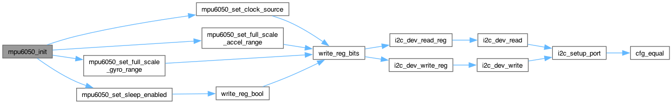

◆ mpu6050_init_desc()
| esp_err_t mpu6050_init_desc | ( | mpu6050_dev_t * | dev, |
| uint8_t | addr, | ||
| i2c_port_t | port, | ||
| gpio_num_t | sda_gpio, | ||
| gpio_num_t | scl_gpio ) |
Initialize device descriptor.
- Parameters
-
dev Device descriptor addr Device I2C address port I2C port sda_gpio SDA GPIO scl_gpio SCL GPIO
- Returns
- ESP_OK on success
< Invalid argument
< Invalid argument


◆ mpu6050_reset()
| esp_err_t mpu6050_reset | ( | mpu6050_dev_t * | dev | ) |
Trigger a full device reset.
A small delay of ~50ms may be desirable after triggering a reset.
- Parameters
-
dev Device descriptor
- Returns
- ESP_OK on success


◆ mpu6050_reset_accelerometer_path()
| esp_err_t mpu6050_reset_accelerometer_path | ( | mpu6050_dev_t * | dev | ) |
Reset accelerometer signal path.
The reset will revert the signal path analog to digital converters and filters to their power up configurations.
- Parameters
-
dev Device descriptor
- Returns
- ESP_OK on success

◆ mpu6050_reset_fifo()
| esp_err_t mpu6050_reset_fifo | ( | mpu6050_dev_t * | dev | ) |
Reset the FIFO.
This bit resets the FIFO buffer when set to 1 while FIFO_EN equals 0. This bit automatically clears to 0 after the reset has been triggered.
- Parameters
-
dev Device descriptor
- Returns
- ESP_OK on success

◆ mpu6050_reset_gyroscope_path()
| esp_err_t mpu6050_reset_gyroscope_path | ( | mpu6050_dev_t * | dev | ) |
Reset gyroscope signal path.
The reset will revert the signal path analog to digital converters and filters to their power up configurations.
- Parameters
-
dev Device descriptor
- Returns
- ESP_OK on success

◆ mpu6050_reset_sensors()
| esp_err_t mpu6050_reset_sensors | ( | mpu6050_dev_t * | dev | ) |
Reset all sensor registers and signal paths.
When set to 1, this bit resets the signal paths for all sensors (gyroscopes, accelerometers, and temperature sensor). This operation will also clear the sensor registers. This bit automatically clears to 0 after the reset has been triggered.
When resetting only the signal path (and not the sensor registers), please use Register 104, SIGNAL_PATH_RESET.
- Parameters
-
dev Device descriptor
- Returns
- ESP_OK on success


◆ mpu6050_reset_temperature_path()
| esp_err_t mpu6050_reset_temperature_path | ( | mpu6050_dev_t * | dev | ) |
Reset temperature sensor signal path.
The reset will revert the signal path analog to digital converters and filters to their power up configurations.
- Parameters
-
dev Device descriptor
- Returns
- ESP_OK on success

◆ mpu6050_self_test()
| esp_err_t mpu6050_self_test | ( | mpu6050_dev_t * | dev, |
| float * | destination ) |
Accelerometer and gyroscope self test.
Check calibration WRT factory settings.
- Parameters
-
dev Device descriptor [out] destination Where the result of the self test will be stored.
- Returns
- ESP_OK on success
< esp_err_t value indicating success (no error)
< esp_err_t value indicating success (no error)
< esp_err_t value indicating success (no error)
< esp_err_t value indicating success (no error)
< esp_err_t value indicating success (no error)
< esp_err_t value indicating success (no error)
< esp_err_t value indicating success (no error)
< esp_err_t value indicating success (no error)
< esp_err_t value indicating success (no error)
< esp_err_t value indicating success (no error)
< esp_err_t value indicating success (no error)
< esp_err_t value indicating success (no error)
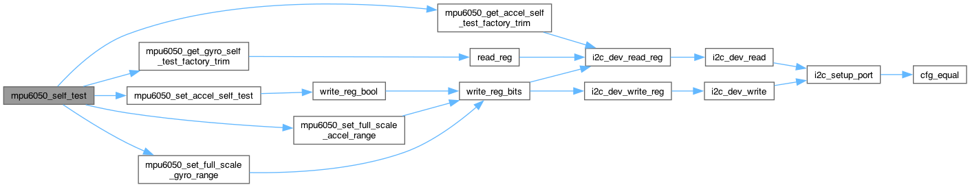
◆ mpu6050_set_accel_fifo_enabled()
| esp_err_t mpu6050_set_accel_fifo_enabled | ( | mpu6050_dev_t * | dev, |
| bool | enabled ) |
Set accelerometer FIFO enabled value.
- Parameters
-
dev Device descriptor enabled New accelerometer FIFO enabled value.
- Returns
- ESP_OK on success


◆ mpu6050_set_accel_offset()
| esp_err_t mpu6050_set_accel_offset | ( | mpu6050_dev_t * | dev, |
| mpu6050_axis_t | axis, | ||
| int16_t | offset ) |
Set offset for accelerometer axis.
Undocumented register/feature
- Parameters
-
dev Device descriptor axis Accelerometer axis offset Offset
- Returns
- ESP_OK on success
< Invalid argument


◆ mpu6050_set_accel_self_test()
| esp_err_t mpu6050_set_accel_self_test | ( | mpu6050_dev_t * | dev, |
| mpu6050_axis_t | axis, | ||
| bool | enabled ) |
Set self-test enabled for accelerometer axis.
- Parameters
-
dev Device descriptor axis Accelerometer axis enabled Self test enabled value
- Returns
- ESP_OK on success
< Invalid argument


◆ mpu6050_set_accelerometer_power_on_delay()
| esp_err_t mpu6050_set_accelerometer_power_on_delay | ( | mpu6050_dev_t * | dev, |
| uint8_t | delay ) |
Set accelerometer power-on delay.
- Parameters
-
dev Device descriptor delay New accelerometer power-on delay (0-3).
- Returns
- ESP_OK on success

◆ mpu6050_set_aux_vddio_level()
| esp_err_t mpu6050_set_aux_vddio_level | ( | mpu6050_dev_t * | dev, |
| mpu6050_vddio_level_t | level ) |
Set the auxiliary I2C supply voltage level.
When set to 1, the auxiliary I2C bus high logic level is VDD. When cleared to 0, the auxiliary I2C bus high logic level is VLOGIC. This does not apply to the MPU6000, which does not have a VLOGIC pin.
- Parameters
-
dev Device descriptor level I2C supply voltage level (0 = VLOGIC, 1 = VDD).
- Returns
- ESP_OK on success

◆ mpu6050_set_clock_output_enabled()
| esp_err_t mpu6050_set_clock_output_enabled | ( | mpu6050_dev_t * | dev, |
| bool | enabled ) |
Set reference clock output enabled status.
- Parameters
-
dev Device descriptor enabled New reference clock output enabled status.
- Returns
- ESP_OK on success

◆ mpu6050_set_clock_source()
| esp_err_t mpu6050_set_clock_source | ( | mpu6050_dev_t * | dev, |
| mpu6050_clock_source_t | source ) |
Set clock source setting.
- Parameters
-
dev Device descriptor source New clock source setting.
- Returns
- ESP_OK on success

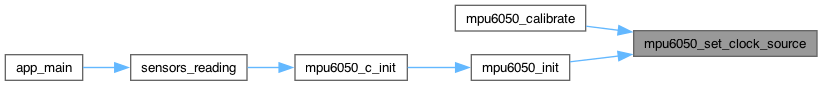
◆ mpu6050_set_dhpf_mode()
| esp_err_t mpu6050_set_dhpf_mode | ( | mpu6050_dev_t * | dev, |
| mpu6050_dhpf_mode_t | mode ) |
Set the high-pass filter configuration.
- Parameters
-
dev Device descriptor mode New high-pass filter configuration
- Returns
- ESP_OK on success

◆ mpu6050_set_dlpf_mode()
| esp_err_t mpu6050_set_dlpf_mode | ( | mpu6050_dev_t * | dev, |
| mpu6050_dlpf_mode_t | mode ) |
Set digital low-pass filter configuration.
- Parameters
-
dev Device descriptor mode New DLFP configuration setting.
- Returns
- ESP_OK on success


◆ mpu6050_set_external_frame_sync()
| esp_err_t mpu6050_set_external_frame_sync | ( | mpu6050_dev_t * | dev, |
| mpu6050_ext_sync_t | sync ) |
Set external FSYNC configuration.
- Parameters
-
dev Device descriptor sync New FSYNC configuration value.
- Returns
- ESP_OK on success

◆ mpu6050_set_external_shadow_delay_enabled()
| esp_err_t mpu6050_set_external_shadow_delay_enabled | ( | mpu6050_dev_t * | dev, |
| bool | enabled ) |
Set external data shadow delay enabled status.
- Parameters
-
dev Device descriptor enabled New external data shadow delay enabled status.
- Returns
- ESP_OK on success

◆ mpu6050_set_fifo_byte()
| esp_err_t mpu6050_set_fifo_byte | ( | mpu6050_dev_t * | dev, |
| uint8_t | data ) |
Write byte to FIFO buffer.
- Parameters
-
dev Device descriptor data New FIFO byte of data.
- Returns
- ESP_OK on success

◆ mpu6050_set_fifo_enabled()
| esp_err_t mpu6050_set_fifo_enabled | ( | mpu6050_dev_t * | dev, |
| bool | enabled ) |
Set FIFO enabled status.
- Parameters
-
dev Device descriptor enabled New FIFO enabled status.
- Returns
- ESP_OK on success


◆ mpu6050_set_freefall_detection_counter_decrement()
| esp_err_t mpu6050_set_freefall_detection_counter_decrement | ( | mpu6050_dev_t * | dev, |
| uint8_t | decrement ) |
Set Free Fall detection counter decrement configuration.
- Parameters
-
dev Device descriptor decrement New decrement configuration value.
- Returns
- ESP_OK on success

◆ mpu6050_set_freefall_detection_duration()
| esp_err_t mpu6050_set_freefall_detection_duration | ( | mpu6050_dev_t * | dev, |
| uint8_t | duration_ms ) |
Set free-fall event duration threshold.
- Parameters
-
dev Device descriptor duration_ms Free-fall duration threshold value, ms
- Returns
- ESP_OK on success

◆ mpu6050_set_freefall_detection_threshold()
| esp_err_t mpu6050_set_freefall_detection_threshold | ( | mpu6050_dev_t * | dev, |
| uint8_t | threshold ) |
Get free-fall event acceleration threshold.
- Parameters
-
dev Device descriptor threshold New free-fall acceleration threshold value (LSB = 2mg).
- Returns
- ESP_OK on success

◆ mpu6050_set_fsync_interrupt_enabled()
| esp_err_t mpu6050_set_fsync_interrupt_enabled | ( | mpu6050_dev_t * | dev, |
| bool | enabled ) |
Set FSYNC pin interrupt enabled setting.
- Parameters
-
dev Device descriptor enabled New FSYNC pin interrupt enabled setting.
- Returns
- ESP_OK on success

◆ mpu6050_set_fsync_interrupt_level()
| esp_err_t mpu6050_set_fsync_interrupt_level | ( | mpu6050_dev_t * | dev, |
| mpu6050_int_level_t | level ) |
Set FSYNC interrupt logic level.
- Parameters
-
dev Device descriptor level New FSYNC interrupt logic level.
- Returns
- ESP_OK on success
< Invalid argument

◆ mpu6050_set_full_scale_accel_range()
| esp_err_t mpu6050_set_full_scale_accel_range | ( | mpu6050_dev_t * | dev, |
| mpu6050_accel_range_t | range ) |
Set full-scale accelerometer range.
- Parameters
-
dev Device descriptor range New full-scale accelerometer range setting
- Returns
- ESP_OK on success
< Invalid argument
< esp_err_t value indicating success (no error)

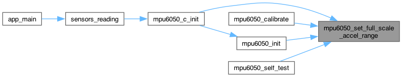
◆ mpu6050_set_full_scale_gyro_range()
| esp_err_t mpu6050_set_full_scale_gyro_range | ( | mpu6050_dev_t * | dev, |
| mpu6050_gyro_range_t | range ) |
Set full-scale gyroscope range.
- Parameters
-
dev Device descriptor range New full-scale gyroscope range value.
- Returns
- ESP_OK on success
< Invalid argument
< esp_err_t value indicating success (no error)

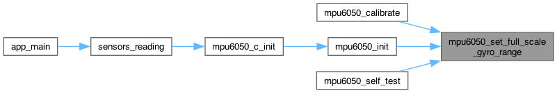
◆ mpu6050_set_gyro_fifo_enabled()
| esp_err_t mpu6050_set_gyro_fifo_enabled | ( | mpu6050_dev_t * | dev, |
| mpu6050_axis_t | axis, | ||
| bool | enabled ) |
Set gyroscope axis FIFO enabled value.
- Parameters
-
dev Device descriptor axis Gyroscope axis enabled New gyroscope axis FIFO enabled value.
- Returns
- ESP_OK on success
< Invalid argument


◆ mpu6050_set_gyro_offset()
| esp_err_t mpu6050_set_gyro_offset | ( | mpu6050_dev_t * | dev, |
| mpu6050_axis_t | axis, | ||
| int16_t | offset ) |
Get offset for gyroscope axis.
Undocumented register/feature
- Parameters
-
dev Device descriptor axis Gyroscope axis offset Offset
- Returns
- ESP_OK on success
< Invalid argument


◆ mpu6050_set_i2c_bypass_enabled()
| esp_err_t mpu6050_set_i2c_bypass_enabled | ( | mpu6050_dev_t * | dev, |
| bool | enabled ) |
Set I2C bypass enabled status.
- Parameters
-
dev Device descriptor enabled New I2C bypass enabled status.
- Returns
- ESP_OK on success

◆ mpu6050_set_i2c_master_mode_enabled()
| esp_err_t mpu6050_set_i2c_master_mode_enabled | ( | mpu6050_dev_t * | dev, |
| bool | enabled ) |
Set I2C Master Mode enabled status.
- Parameters
-
dev Device descriptor enabled New I2C Master Mode enabled status.
- Returns
- ESP_OK on success


◆ mpu6050_set_int_enabled()
| esp_err_t mpu6050_set_int_enabled | ( | mpu6050_dev_t * | dev, |
| uint8_t | ints ) |
Set full interrupt enabled status.
Full register byte for all interrupts, for quick writing. Each bit will be set 0 for disabled, 1 for enabled.
- Parameters
-
dev Device descriptor ints Combination of mpu6050_int_source_t flags
- Returns
- ESP_OK on success


◆ mpu6050_set_interrupt_drive()
| esp_err_t mpu6050_set_interrupt_drive | ( | mpu6050_dev_t * | dev, |
| mpu6050_int_drive_t | drive ) |
Set interrupt drive mode.
- Parameters
-
dev Device descriptor drive New interrupt drive mode
- Returns
- ESP_OK on success
< Invalid argument

◆ mpu6050_set_interrupt_latch()
| esp_err_t mpu6050_set_interrupt_latch | ( | mpu6050_dev_t * | dev, |
| mpu6050_int_latch_t | latch ) |
Set interrupt latch mode.
- Parameters
-
dev Device descriptor latch New latch mode
- Returns
- ESP_OK on success
< Invalid argument

◆ mpu6050_set_interrupt_latch_clear()
| esp_err_t mpu6050_set_interrupt_latch_clear | ( | mpu6050_dev_t * | dev, |
| bool | clear ) |
Set interrupt latch clear mode.
- Parameters
-
dev Device descriptor clear New latch clear mode (false = status-read-only, true = any-register-read).
- Returns
- ESP_OK on success

◆ mpu6050_set_interrupt_mode()
| esp_err_t mpu6050_set_interrupt_mode | ( | mpu6050_dev_t * | dev, |
| mpu6050_int_level_t | mode ) |
Set interrupt logic level mode.
- Parameters
-
dev Device descriptor mode New interrupt mode.
- Returns
- ESP_OK on success
< Invalid argument

◆ mpu6050_set_master_clock_speed()
| esp_err_t mpu6050_set_master_clock_speed | ( | mpu6050_dev_t * | dev, |
| mpu6050_i2c_master_clock_t | clk_spd ) |
Set I2C master clock speed.
- Parameters
-
dev Device descriptor clk_spd Current I2C master clock speed.
- Returns
- ESP_OK on success

◆ mpu6050_set_motion_detection_counter_decrement()
| esp_err_t mpu6050_set_motion_detection_counter_decrement | ( | mpu6050_dev_t * | dev, |
| uint8_t | decrement ) |
Set Motion detection counter decrement configuration.
- Parameters
-
dev Device descriptor decrement New decrement configuration value.
- Returns
- ESP_OK on success

◆ mpu6050_set_motion_detection_duration()
| esp_err_t mpu6050_set_motion_detection_duration | ( | mpu6050_dev_t * | dev, |
| uint8_t | duration ) |
Set motion detection event duration threshold.
- Parameters
-
dev Device descriptor duration New motion detection duration threshold value, ms
- Returns
- ESP_OK on success

◆ mpu6050_set_motion_detection_threshold()
| esp_err_t mpu6050_set_motion_detection_threshold | ( | mpu6050_dev_t * | dev, |
| uint8_t | threshold ) |
Set motion detection event acceleration threshold.
- Parameters
-
dev Device descriptor threshold New motion detection acceleration threshold value (LSB = 2mg)
- Returns
- ESP_OK on success

◆ mpu6050_set_multi_master_enabled()
| esp_err_t mpu6050_set_multi_master_enabled | ( | mpu6050_dev_t * | dev, |
| bool | enabled ) |
Set multi-master enabled value.
- Parameters
-
dev Device descriptor enabled New multi-master enabled value.
- Returns
- ESP_OK on success


◆ mpu6050_set_rate()
| esp_err_t mpu6050_set_rate | ( | mpu6050_dev_t * | dev, |
| uint8_t | rate ) |
Set gyroscope output rate divider.
- Parameters
-
dev Device descriptor rate New sample rate divider.
- Returns
- ESP_OK on success


◆ mpu6050_set_slave_4_interrupt_enabled()
| esp_err_t mpu6050_set_slave_4_interrupt_enabled | ( | mpu6050_dev_t * | dev, |
| bool | enabled ) |
Set the enabled value for Slave 4 transaction interrupts.
- Parameters
-
dev Device descriptor enabled New enabled value for Slave 4 transaction interrupts.
- Returns
- ESP_OK on success

◆ mpu6050_set_slave_4_master_delay()
| esp_err_t mpu6050_set_slave_4_master_delay | ( | mpu6050_dev_t * | dev, |
| uint8_t | delay ) |
Set Slave 4 master delay value.
- Parameters
-
dev Device descriptor delay New Slave 4 master delay value.
- Returns
- ESP_OK on success

◆ mpu6050_set_slave_4_output_byte()
| esp_err_t mpu6050_set_slave_4_output_byte | ( | mpu6050_dev_t * | dev, |
| uint8_t | data ) |
Set new byte to write to Slave 4. This register stores the data to be written into the Slave 4. If I2C_SLV4_RW is set 1 (set to read), this register has no effect.
- Parameters
-
dev Device descriptor data New byte to write to Slave 4.
- Returns
- ESP_OK on success

◆ mpu6050_set_slave_address()
| esp_err_t mpu6050_set_slave_address | ( | mpu6050_dev_t * | dev, |
| mpu6050_slave_t | num, | ||
| uint8_t | address ) |
Set the I2C address of the specified slave.
- Parameters
-
dev Device descriptor num Slave number (0-4) address New address for specified slave.
- Returns
- ESP_OK on success
< Invalid argument

◆ mpu6050_set_slave_data_length()
| esp_err_t mpu6050_set_slave_data_length | ( | mpu6050_dev_t * | dev, |
| mpu6050_slave_t | num, | ||
| uint8_t | length ) |
Set number of bytes to read for the specified slave.
- Parameters
-
dev Device descriptor num Slave number (0-4). length Number of bytes to read for specified slave.
- Returns
- ESP_OK on success
< Invalid argument

◆ mpu6050_set_slave_delay_enabled()
| esp_err_t mpu6050_set_slave_delay_enabled | ( | mpu6050_dev_t * | dev, |
| mpu6050_slave_t | num, | ||
| bool | enabled ) |
Set slave delay enabled status.
- Parameters
-
dev Device descriptor num Slave number (0-4). enabled New slave delay enabled status.
- Returns
- ESP_OK on success
< Invalid argument

◆ mpu6050_set_slave_enabled()
| esp_err_t mpu6050_set_slave_enabled | ( | mpu6050_dev_t * | dev, |
| mpu6050_slave_t | num, | ||
| bool | enabled ) |
Set the enabled value for the specified slave.
- Parameters
-
dev Device descriptor num Slave number (0-4). enabled New enabled value for specified slave.
- Returns
- ESP_OK on success
< Invalid argument

◆ mpu6050_set_slave_fifo_enabled()
| esp_err_t mpu6050_set_slave_fifo_enabled | ( | mpu6050_dev_t * | dev, |
| mpu6050_slave_t | num, | ||
| bool | enabled ) |
Set Slave FIFO enabled value.
- Parameters
-
dev Device descriptor num Slave number (0-3) enabled New Slave FIFO enabled value.
- Returns
- ESP_OK on success
< Invalid argument

◆ mpu6050_set_slave_output_byte()
| esp_err_t mpu6050_set_slave_output_byte | ( | mpu6050_dev_t * | dev, |
| mpu6050_slave_t | num, | ||
| uint8_t | data ) |
Write byte to Data Output container for specified slave.
This register holds the output data written into Slave when Slave is set to write mode. For further information regarding Slave control, please refer to Registers 37 to 39 and immediately following.
- Parameters
-
dev Device descriptor num Slave number (0-3). data Byte to write.
- Returns
- ESP_OK on success
< Invalid argument

◆ mpu6050_set_slave_read_write_transition_enabled()
| esp_err_t mpu6050_set_slave_read_write_transition_enabled | ( | mpu6050_dev_t * | dev, |
| bool | enabled ) |
Set slave read/write transition enabled value.
- Parameters
-
dev Device descriptor enabled New slave read/write transition enabled value.
- Returns
- ESP_OK on success

◆ mpu6050_set_slave_register()
| esp_err_t mpu6050_set_slave_register | ( | mpu6050_dev_t * | dev, |
| mpu6050_slave_t | num, | ||
| uint8_t | reg ) |
Set the active internal register for the specified slave.
- Parameters
-
dev Device descriptor num Slave number (0-4). reg New active register for specified slave.
- Returns
- ESP_OK on success
< Invalid argument

◆ mpu6050_set_slave_word_byte_swap()
| esp_err_t mpu6050_set_slave_word_byte_swap | ( | mpu6050_dev_t * | dev, |
| mpu6050_slave_t | num, | ||
| bool | enabled ) |
Set word pair byte-swapping enabled for the specified slave.
- Parameters
-
dev Device descriptor num Slave number (0-4). enabled New word pair byte-swapping enabled value for specified slave.
- Returns
- ESP_OK on success
< Invalid argument

◆ mpu6050_set_slave_word_group_offset()
| esp_err_t mpu6050_set_slave_word_group_offset | ( | mpu6050_dev_t * | dev, |
| mpu6050_slave_t | num, | ||
| bool | enabled ) |
Set word pair grouping order offset for the specified slave.
- Parameters
-
dev Device descriptor num Slave number (0-4). enabled New word pair grouping order offset for specified slave.
- Returns
- ESP_OK on success
< Invalid argument

◆ mpu6050_set_slave_write_mode()
| esp_err_t mpu6050_set_slave_write_mode | ( | mpu6050_dev_t * | dev, |
| mpu6050_slave_t | num, | ||
| bool | mode ) |
Set write mode for the specified slave.
- Parameters
-
dev Device descriptor num Slave number (0-4). mode Write mode: false - register address + data, true - data only
- Returns
- ESP_OK on success
< Invalid argument

◆ mpu6050_set_sleep_enabled()
| esp_err_t mpu6050_set_sleep_enabled | ( | mpu6050_dev_t * | dev, |
| bool | enabled ) |
Set sleep mode status.
- Parameters
-
dev Device descriptor enabled New sleep mode enabled status.
- Returns
- ESP_OK on success


◆ mpu6050_set_standby_accel_enabled()
| esp_err_t mpu6050_set_standby_accel_enabled | ( | mpu6050_dev_t * | dev, |
| mpu6050_axis_t | axis, | ||
| bool | enabled ) |
Set accelerometer axis standby enabled status.
- Parameters
-
dev Device descriptor axis Accelerometer axis. enabled Accelerometer axis standby enabled status.
- Returns
- ESP_OK on success
< Invalid argument

◆ mpu6050_set_standby_gyro_enabled()
| esp_err_t mpu6050_set_standby_gyro_enabled | ( | mpu6050_dev_t * | dev, |
| mpu6050_axis_t | axis, | ||
| bool | enabled ) |
Set gyroscope axis standby enabled status.
If enabled, the axis will not gather or report data (or use power).
- Parameters
-
dev Device descriptor axis Gyroscope axis. enabled Gyroscope axis standby enabled status.
- Returns
- ESP_OK on success
< Invalid argument

◆ mpu6050_set_temp_fifo_enabled()
| esp_err_t mpu6050_set_temp_fifo_enabled | ( | mpu6050_dev_t * | dev, |
| bool | enabled ) |
Set temperature FIFO enabled value.
- Parameters
-
dev Device descriptor enabled New temperature FIFO enabled value.
- Returns
- ESP_OK on success


◆ mpu6050_set_temp_sensor_enabled()
| esp_err_t mpu6050_set_temp_sensor_enabled | ( | mpu6050_dev_t * | dev, |
| bool | enabled ) |
Set temperature sensor enabled status.
Note: this register stores the disabled value, but for consistency with the rest of the code, the function is named and used with standard true/false values to indicate whether the sensor is enabled or disabled, respectively.
- Parameters
-
dev Device descriptor enabled New temperature sensor enabled status.
- Returns
- ESP_OK on success

◆ mpu6050_set_wait_for_external_sensor_enabled()
| esp_err_t mpu6050_set_wait_for_external_sensor_enabled | ( | mpu6050_dev_t * | dev, |
| bool | enabled ) |
Set wait-for-external-sensor-data enabled value.
- Parameters
-
dev Device descriptor enabled New wait-for-external-sensor-data enabled value.
- Returns
- ESP_OK on success

◆ mpu6050_set_wake_cycle_enabled()
| esp_err_t mpu6050_set_wake_cycle_enabled | ( | mpu6050_dev_t * | dev, |
| bool | enabled ) |
Set wake cycle enabled status.
- Parameters
-
dev Device descriptor enabled Wake cycle enabled status.
- Returns
- ESP_OK on success

◆ mpu6050_set_wake_frequency()
| esp_err_t mpu6050_set_wake_frequency | ( | mpu6050_dev_t * | dev, |
| mpu6050_wake_freq_t | frequency ) |
Set wake frequency in Accel-Only Low Power Mode.
- Parameters
-
dev Device descriptor frequency New wake frequency.
- Returns
- ESP_OK on success

◆ mpu6050_set_zero_motion_detection_duration()
| esp_err_t mpu6050_set_zero_motion_detection_duration | ( | mpu6050_dev_t * | dev, |
| uint8_t | duration ) |
Set zero motion detection event duration threshold.
- Parameters
-
dev Device descriptor duration New zero motion detection duration threshold value (LSB = 64ms)
- Returns
- ESP_OK on success

◆ mpu6050_set_zero_motion_detection_threshold()
| esp_err_t mpu6050_set_zero_motion_detection_threshold | ( | mpu6050_dev_t * | dev, |
| uint8_t | threshold ) |
Set zero motion detection event acceleration threshold.
- Parameters
-
dev Device descriptor threshold New zero motion detection acceleration threshold value (LSB = 2mg)
- Returns
- ESP_OK on success

◆ mpu6050_switch_spie_enabled()
| esp_err_t mpu6050_switch_spie_enabled | ( | mpu6050_dev_t * | dev, |
| bool | enabled ) |
Switch from I2C to SPI mode (MPU-6000 only).
If this is set, the primary SPI interface will be enabled in place of the disabled primary I2C interface.
Note: This driver does not support SPI mode!
- Parameters
-
dev Device descriptor enabled New switch SPIE Mode enabled status.
- Returns
- ESP_OK on success
